|
|
|
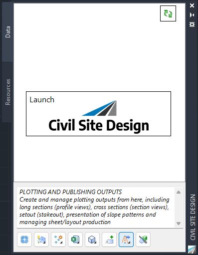
Launch
|
If this is a new project, click on this button to initialize the Toolspace to display the object listing. |
|
 Refresh (Update) Refresh (Update)
|
If additional Civil 3D Alignments are created in the drawing, click this button to include them in the Alignments object collection.
If newly created Strings, Surfaces, Models or Corridors (Civil 3D) are not displaying, click this button to display them in the object collection.
A Thread can be set to run whenever this button is clicked.
This command also executes the Update All command. |
|
Panel Tabs
|
Tabs are displayed along the edge of the Toolspace. |
|
Data tab
|
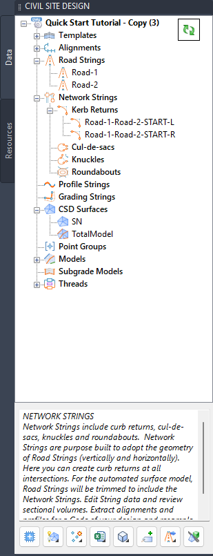
Contains all Civil Site Design data, listed in a tree view arranged by object type.
|
|
 [Drawing Name] [Drawing Name]
|
Right click commands:
|
Set Civil 3D Styles (Civil 3D only)
|
Set the Civil 3D Styles to apply to Civil 3D objets created by the software: Surfaces, Profiles, Profile Views and Alignments.br>Click to open the Set Civil 3D Styles command. |
|
Drawing Settings
|
Manages the overall behaviour of Civil Site Design.
Click to open the Active Drawing Settings command. |
|
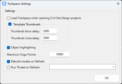
Toolspace Settings
|
Includes functionality to manage the display of the Toolspace. Inputs include:
|
|
|
Load Toolspace when opening Civil Site Design Project
|
If toggled on, when a drawing is opened it is scanned for Civil Site Design data. If the drawing contains Civil Site Design data, the toolspace will open. |
|
Template Thumbnails
|
An image of each Template can be displayed on hover over the Template in the Toolspace. Toggle this option on to enable thumbnail image display when hovering on Templates |
|
Thumbnail show delay
|
Sets a time in milliseconds before displaying a Template thumbnail |
|
Thumbnail close delay
|
Sets a time in milliseconds to display the thumbnail after hovering on the Template. After this time the thumbnail will disappear from screen. |
|
Object Highlighting
|
Tick on to enable object highlighting in the drawing when hovering on an object. |
| Maximum Cogo Points |
The Toolspace redraw and display can slow when there are a large number of objects listed. It is highly recommended to limit the number of Cogo Points displayed in the Toolspace to prevent unacceptable lag. The additional points will not be represented in the Toolspace. |
|
Rebuild models on Refresh
|
When ticked on, running Update All, or clicking the Refresh button on the Toolspace, will rebuild all built Models |
| Run Thread on Refresh |
Select a Thread from the list to include execution of the Thread when the Refresh button is clicked on the Toolspace. |
|
OK
|
Apply and exit.
|
|
|
Project Storage
|
Enables saving of the Civil Site Design data inside the drawing (.dwg) file and management of where the data is stored during editing.
Click to open the Project Storage command. |
Language Settings |
Enables translation of the product to different languages.
Click to open the
Language Settings form. |
|
Rebuild Options
|
Provides access to rebuild options that improve performance.
Click to open the Rebuild Options form. |
| Grip Settings |
Manage display of grips when Civil Site Design objects are selected.
Click to open the Grip Settings form. |
|
String Defaults
|
Sets defaults for Point Code Settings, Survey String Settings and Default Point Style for alpha and numeric coded COGO points.
Click to open the String Defaults form. |
|
Point Code Set
|
Sets up Point Code Settings to establish layers and point styles to apply based on COGO point descriptions.
Click to open the Point Code Settings form. |
| Point Styles |
Point Styles set how COGO points are displayed as well as available point properties
Click to open the Point Styles form. |
| Point Formats |
Establishes the file format for importing/exporting points and controls how COGO point descriptions are interpreted as Code, String Number and other point properties
Click to open the Point Formats form. |
| Point Property Display |
Allows select point display properties to be hidden for all points in the drawing.
Click to open the Point Property Display form. |
|
Survey String Settings
|
Establishes how survey strings are connected based on COGO point descriptions.
Click to open the Survey String Settings form. |
| Survey String Parameters |
Set parameters that may be applied to Point descriptions to change the way survey linework is connected between points.
Click to open the Survey String Parameters form. |
| Replace Code Settings |
Applies bulk changes to point codes. This establishes the code pairs.
Click to open the Replace Code Settings form. |
| Group Table Styles |
Table settings for output of Cogo Point and Survey String tables for selected Point Groups.
Click to open the Point Group Table Settings command. |
|
Image from Satellite
|
Import a background image from the web and add as a .png XREF.
Click to open the Image from Satellite form. |
|
Surface from Satellite
|
Import a surface and background image from the web.
Click to open the Surface from Satellite form. |
|
|
 Templates Collection Templates Collection
|
Right click commands:
|
Template Editor
|
Manage typical cross sections applied to Strings.
Click to start the Create/Edit Templates command. |
|
 Intelligent Sections Intelligent Sections
|
Manage Intelligent Section templates.
Click to start the Intelligent Sections command. |
|
|
/  Template Template
|
Icon display changes if the Template is being referenced by a String.
Right click commands:
|
Edit Template
|
Hover over each Template to see an image preview of the Template. Click on a different object in the Toolspace to hide the image or wait - it will disappear after a short time.
Click to start the Create/Edit Section Templates command and open to the highlighted Template. |
|
|
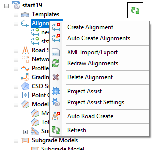
 Alignments Collection Alignments Collection
|
Right click commands:
|
Create Alignment
[Not Civil 3D]
|
Create an alignment using polyline geometry in the drawing.
Click to start the Create Alignment command. |
|
Create Best Fit Alignment
[Not Civil 3D]
|
Create an alignment using COGO Point or polyline geometry in the drawing.
Click to start the Best Fit Alignment command. |
|
Auto Create Alignments
[Not Civil 3D]
|
Create multiple alignments, using all polylines on a single layer.
Click to start the Auto Create Alignments command. |
|
XML Import/Export
[Not Civil 3D]
|
Alignments can be imported or exported using LandXML files.
Click to start the XML Import/Export command. |
|
Redraw Alignments
[Not Civil 3D]
|
This will redraw alignments in the drawing. |
Delete Alignment
[Not Civil 3D] |
This command deletes alignments.
Click to start the Delete Alignment command. |
|
Project Assist
|
Project Assist automates the model creation process by intelligently assessing alignment usage and providing a workflow for creating Strings and Models.
Click to start the Project Assist command. |
|
Project Assist Settings
|
Access settings to manage how Project Assist operates.
Click to start the Project Assist Settings command. |
|
Auto Road Create
|
Enables creation of Road Strings from all alignments in the drawing.
Click to start the Auto Create Roads command. |
|
Refresh
|
Click to Refresh the list of alignments. This will be required if a new Civil 3D Alignment is created or an alignment Name is changed.
Note: If a String has been created from the alignment, use the Rename String command to change the name of the alignment, so that the String name and any reference objects can be updated.
|
|
|
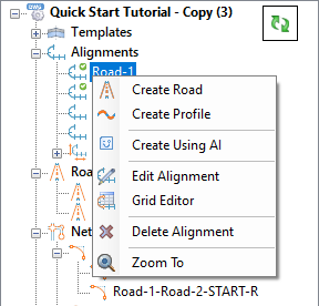
/  Alignment Alignment
|
Icon display changes if the alignment is being referenced by a String
Right click commands:
|
Create Road
|
Create a Road String from the alignment.
Click to start the Create Road command. |
|
Create Profile
|
Create a Profile String from the alignment.
Click to start the Profile String command. |
|
Create Using AI
|
Let Project Assist assess and recommend how to include the Alignment in the String Models.
Click to start the Create Using AI command. |
|
Edit Alignment
[Not Civil 3D]
|
Click to open the Edit Alignment form for the selected alignment.
[Not available for Civil 3D alignments] |
|
Grid Editor
[Not Civil 3D]
|
Opens the grid editor to edit alignment geometry.
Click to open the Alignment Grid Editor form. |
|
Delete Alignment
[Not Civil 3D]
|
Click to delete the current alignment. A message will display to confirm deletion.
If the alignment is being used as a String, the alignment will not be deleted and a message will display. |
|
Zoom To
|
Zooms to the start of the alignment in the drawing |
|
|
 Parametric Alignments Parametric Alignments
|
Lists alignments created by the software - typically these describe kerb returns, cul-de-sacs and knuckles
|
|
Parametric Alignment
|
Right click commands:
|
Edit
|
Type:
Kerb Return String: starts the Edit Kerb Return command for the selected alignment String
Cul-de-sac String: starts the Edit Cul-de-sac command for the selected alignment String
Knuckle String: starts the Edit Knuckle command for the selected alignment String |
|
Vertical Grading Editor
|
Opens the Vertical Grading Editor for editing of the vertical geometry for the selected alignment String. |
|
Cross Section Viewer
|
Opens the Cross Section Viewer for the selected alignment String at the start of the String |
|
Design Data Form
|
Opens the Design Data Form for the selected alignment String |
|
Zoom To
|
Zooms to the start of the alignment in the drawing |
|
|
 Road Strings Collection Road Strings Collection
|
Right click commands:
| Create/Edit Road |
Starts the Create/Edit Road command, prompting for selection of an alignment in the drawing. |
| Vertical Grading Editor |
Starts the Vertical Grading Editor command, prompting for selection of an alignment in the drawing. |
| Cross Section Viewer |
Starts the Cross Section Viewer command, prompting for selection of an alignment and then a position along the alignment for the section to display. |
| Design Data Form |
Starts the Design Data Form command, prompting for selection of an alignment in the drawing. |
| Volume Report |
Starts the sectional Volume Report command. |
| Create/Update Civil 3D Profiles |
[Civil 3D only]
Creates Civil 3D Profiles and Civil 3D Profile Views in the drawing.
Click to start the Create/Update Civil 3D Profiles command
Two Profiles will be created:
- Design-[Alignment Name] - this represents the design profile from Civil Site Design
- Existing-[Alignment Name] - this represents the existing ground profile from Civil Site Design
|
| Create/Update Projected Profiles |
[Civil 3D only]
Projects other Strings onto a main alignment as projected Civil 3D Profiles (complete with IP's and vertical curves).
Click to start the Projected Profiles command |
| Create/Update Reference Profiles |
Create Strings (profiles) that reference codes on a main road. Reference profiles adopt the horizontal geometry of the main road alignment. Vertically, reference profiles copy the main string vertical design for user controlled chainage ranges.
Click to start the Reference Profiles command. |
| Update from Civil 3D Profiles |
[Civil 3D only]
Updates the Civil Site Design String vertical geometry using the Civil 3D Profile geometry, including re-connection of all kerb return, cul-de-sac and knuckle elevations.
Click to start the Update from Civil 3D Profiles command.
Note: the profile names must match the naming convention as per the Create/Update Civil 3D Profiles command.
|
| Profiles from Code |
Extracts a selected Code from a Civil Site Design String to create a Civil 3D alignment and profile.
Click to start the Strings from Code command. |
| Multi String Edit |
Resample multiple Strings at once.
Click to start the Multi String Edit command. |
| Switch Roads/Profiles |
Convert Road Strings to Profile Strings, and vice versa.
Click to open the Switch Roads/Profiles command. |
| Nominate Side Road |
This command allows cross road priority to be changes.
Click to open the Nominate Side Road command. |
| Intersection Manager |
Manage all intersections and kerb returns.
Click to start the Intersection Manager command. |
| Side Road VC Controls |
Side Roads can have an automatic vertical curve applied to transition from the cross fall of the main road into the side road profile (vertical grading). This command allows this behaviour to be changed for all intersections.
Click to open the Side Road VC Controls (Auto Ease Properties) command. |
| Use Other Road Chainages |
Allows chainages to be referenced from another string.
Click to open the Use Other Road Chainages command. |
|
|
Road String
|
Right click commands:
|
Vertical Grading Editor
|
Opens the Vertical Grading Editor for editing of the vertical geometry for the selected String. |
|
Cross Section Viewer
|
Opens the Cross Section Viewer for the selected String at the start of the String |
|
Design Data Form
|
Opens the Design Data Form for the selected String |
|
Resample Sections
|
Resampling sections is the equivalent of reopening the Create Road form, allowing change of multiple aspects of the String.
Click to start the Resample Sections command for the selected String |
|
Insert Sections
|
Add/Remove section sampling for the selected String
Click to start the Insert Sections command for the selected String |
|
Shift Chainages
|
Shift the chainages of strings and models.
Click to start the Shift Chainages command for the selected String |
|
Sectional Volumes
|
Obtain immediate sectional volumes for the selected string.
Click to start the Volumes Report command for the selected String |
|
Superelevation
|
Apply superelevation to the selected String.
Click to start the Superelevation command for the selected String. |
|
Plot Long Section
|
Plot long sections for the selected String |
|
Plot Cross Section
|
Plot cross sections for the selected String |
|
Sectional Volumes
|
Obtain immediate sectional volumes for the selected string.
Click to start the Volumes Report command for the selected String |
|
Delete String
|
Deletes the selected String and updates the TotalModel (Automatic Road Network model). |
|
Toggle on/off Section Lines
|
Turns on/off the display of the section lines for a string. |
|
Zoom To
|
Zooms to the start of the alignment in the drawing |
|
|
 Network Strings Collection Network Strings Collection
|
Right click commands:
|
Auto Kerb Returns
|
Starts the Auto Kerb Returns command. This command will find all tee and cross road intersections and add kerb returns at each quadrant. |
| Intersection Manager |
Manage all intersections and kerb returns.
Click to start the Intersection Manager command. |
| Vertical Grading Editor |
Starts the Vertical Grading Editor command, prompting for selection of an alignment in the drawing. |
| Cross Section Viewer |
Starts the Cross Section Viewer command, prompting for selection of an alignment and then a position along the alignment for the section to display. |
| Design Data Form |
Starts the Design Data Form command, prompting for selection of an alignment in the drawing. |
| Volume Report |
Starts the sectional Volume Report command. |
|
Create/Edit Kerb Return
|
Starts the Create/Edit Kerb Return command. At the prompt pick an intersection quadrant to add a kerb return. |
|
Create/Edit Cul-de-sac
|
Starts the Create/Edit Cul-de-sac command. Press Enter to create a new cul-de-sac or pick a created cul-de-sac alignment to edit. |
|
Create/Edit Knuckle
|
Starts the Create/Edit Knuckle command. Press Enter to create a new knuckle string or pick a created knuckle alignment to edit. |
| Create/Edit Roundabout |
Starts the Create/Edit Roundabout command. |
| Profiles from Code |
Extracts a selected Code from a Civil Site Design String to create a Civil 3D alignment and profile.
Click to start the Strings from Code command. |
| Multi String Edit |
Resample multiple Strings at once.
Click to start the Multi String Edit command. |
|
|
 Kerb Returns Collection Kerb Returns Collection
|
Right click commands:
|
Create/Edit Kerb Return
|
Starts the Create/Edit Kerb Return command. At the prompt pick an intersection quadrant to add a kerb return. |
| Intersection Manager |
Manage all intersections and kerb returns.
Click to start the Intersection Manager command. |
|
Kerb Return Design Controls
|
By default, the kerb return vertical grading is set to adopt the start/end elevations, the start/end grades and to create either a single IP or two IP's, with vertical curve length equal to half the length of the kerb return. Users can edit this, which disables the automated design. This command sets the vertical design controls on all created kerb returns.
Click to start the Kerb Design Controls command. |
|
|
Kerb Return
|
Right click commands:
|
Edit Kerb Return
|
Opens the Edit Kerb Return form for the selected String. |
| Vertical Grading Editor |
Open the Vertical Grading Editor for the selected String. |
|
Cross Section Viewer
|
Opens the Cross Section Viewer for the selected alignment String at the start of the String |
|
Design Data Form
|
Opens the Design Data Form for the selected alignment String |
|
Resample Sections
|
Resampling sections is the equivalent of reopening the Create Road form, allowing change of multiple aspects of the String.
Click to start the Resample Sections command for the selected String |
|
Sectional Volumes
|
Obtain immediate sectional volumes for the selected string.
Click to start the Volumes Report command for the selected String |
|
Delete String
|
Deletes the selected String and updates the TotalModel (Automatic Road Network model). |
|
Zoom To
|
Zooms to the start of the alignment in the drawing |
|
|
 Cul-de-sacs Collection Cul-de-sacs Collection
|
Right click commands:
|
Create/Edit Cul-de-sac
|
Starts the Create/Edit Cul-de-sac command. Press Enter to create a new cul-de-sac or pick a created cul-de-sac alignment to edit. |
| Cul-de-sac Design Controls |
By default, the cul-de-sac vertical grading is set to adopt the start/end elevations, the start/end grades and to create either a single IP or two IP's, with vertical curve length equal to half the length of the cul-de-sac. Users can edit this, which disables the automated design. This command sets the vertical design controls on all created cul-de-sacs.
Click to start the Cul-de-sac Design Controls command. |
|
|
Cul-de-sac
|
Right click commands:
|
Edit Cul-de-sac
|
Opens the Edit Cul-de-sac form for the selected String |
| Vertical Grading Editor |
Open the Vertical Grading Editor for the selected String. |
|
Cross Section Viewer
|
Opens the Cross Section Viewer for the selected alignment String at the start of the String |
|
Design Data Form
|
Opens the Design Data Form for the selected alignment String |
|
Resample Sections
|
Resampling sections is the equivalent of reopening the Create Road form, allowing change of multiple aspects of the String.
Click to start the Resample Sections command for the selected String |
|
Sectional Volumes
|
Obtain immediate sectional volumes for the selected string.
Click to start the Volumes Report command for the selected String |
|
Delete String
|
Deletes the selected String and updates the TotalModel (Automatic Road Network model). |
|
Zoom To
|
Zooms to the start of the alignment in the drawing |
|
|
 Knuckle Collection Knuckle Collection
|
Right click commands:
|
Create/Edit Knuckle
|
Starts the Create/Edit Knuckle command. Press Enter to create a new knuckle string or pick a created knuckle alignment to edit. |
|
|
Knuckle
|
Right click commands:
|
Edit Knuckle
|
Opens the Edit Knuckle form for the selected String. |
| Vertical Grading Editor |
Open the Vertical Grading Editor for the selected String. |
|
Cross Section Viewer
|
Opens the Cross Section Viewer for the selected alignment String at the start of the String |
|
Design Data Form
|
Opens the Design Data Form for the selected alignment String |
|
Resample Sections
|
Resampling sections is the equivalent of reopening the Create Road form, allowing change of multiple aspects of the String.
Click to start the Resample Sections command for the selected String |
|
Sectional Volumes
|
Obtain immediate sectional volumes for the selected string.
Click to start the Volumes Report command for the selected String |
|
Delete String
|
Deletes the selected String and updates the TotalModel (Automatic Road Network model). |
|
Zoom To
|
Zooms to the start of the alignment in the drawing |
|
|
 Roundabouts Collection Roundabouts Collection
|
Right click commands:
|
|
Roundabout
|
Right click commands:
| Edit Roundabout |
Opens the Edit Roundabout form for the selected String. |
|
Cross Section Viewer
|
Opens the Cross Section Viewer for the selected alignment String at the start of the String |
|
Design Data Form
|
Opens the Design Data Form for the selected alignment String |
|
Resample Sections
|
Resampling sections is the equivalent of reopening the Create Road form, allowing change of multiple aspects of the String.
Click to start the Resample Sections command for the selected String |
|
Sectional Volumes
|
Obtain immediate sectional volumes for the selected string.
Click to start the Volumes Report command for the selected String |
|
Delete String
|
Deletes the selected String and updates the TotalModel (Automatic Road Network model). |
|
Zoom To
|
Zooms to the start of the alignment in the drawing |
|
|
 Profile Strings Collection Profile Strings Collection
|
Right click commands:
| Create/Edit Profile |
Starts the Create/Edit Road command, prompting for selection of an alignment in the drawing. |
| Vertical Grading Editor |
Starts the Vertical Grading Editor command, prompting for selection of an alignment in the drawing. |
| Cross Section Viewer |
Starts the Cross Section Viewer command, prompting for selection of an alignment and then a position along the alignment for the section to display. |
| Design Data Form |
Starts the Design Data Form command, prompting for selection of an alignment in the drawing. |
| Volume Report |
Starts the sectional Volume Report command. |
| Draped Strings |
Draped Strings are set to adopt the elevations of a selected surface, with elevations calculated at a set sampling rate.
Click to start the Draped Strings command. |
| Update Draped Strings |
If the alignment geometry or the surface referenced by the Draped String/s is updated, this command resets the elevations to match the referenced surface elevations. |
Create/Update Civil 3D Profiles
[Civil 3D only] |
Creates Civil 3D Profiles and Civil 3D Profile Views in the drawing.
Click to start the Create/Update Civil 3D Profiles command
Two Profiles will be created:
- Design-[Alignment Name] - this represents the design profile from Civil Site Design
- Existing-[Alignment Name] - this represents the existing ground profile from Civil Site Design
|
Update from Civil 3D Profiles
[Civil 3D only] |
Updates the Civil Site Design String vertical geometry using the Civil 3D Profile geometry, including re-connection of all kerb return, cul-de-sac and knuckle elevations.
Click to start the Update from Civil 3D Profiles command.
Note: the profile names must match the naming convention as per the Create/Update Civil 3D Profiles command.
|
| Profiles from Code |
Extracts a selected Code from a Civil Site Design String to create a Civil 3D alignment and profile.
Click to start the Strings from Code command. |
| Multi String Edit |
Resample multiple Strings at once.
Click to start the Multi String Edit command. |
|
Toggle on/off Section Lines
|
Turns on/off the display of the section lines for a string. |
| Switch Roads/Profiles |
Allows users to switch a Road String (supporting intersection connections and kerb returns) to a Profile String, and vice versa.
Click to start the Switch Roads and Profiles command. |
|
|
Profile String
|
Right click commands:
|
Vertical Grading Editor
|
Opens the Vertical Grading Editor for editing of the vertical geometry for the selected String. |
|
Cross Section Viewer
|
Opens the Cross Section Viewer for the selected alignment String at the start of the String |
|
Design Data Form
|
Opens the Design Data Form for the selected alignment String |
|
Resample Sections
|
Resampling sections is the equivalent of reopening the Create Road form, allowing change of multiple aspects of the String.
Click to start the Resample Sections command for the selected String |
|
Insert Sections
|
Add/Remove section sampling for the selected String
Click to start the Insert Sections command for the selected String |
|
Shift Chainages
|
Shift the chainages of strings and models.
Click to start the Shift Chainages command for the selected String |
|
Sectional Volumes
|
Obtain immediate sectional volumes for the selected string.
Click to start the Volumes Report command for the selected String |
|
Delete String
|
Deletes the selected String. |
|
Toggle on/off Section Lines
|
Turns on/off the display of the section lines for a string. |
|
Zoom To
|
Zooms to the start of the alignment in the drawing |
|
|
 Grading Strings Collection Grading Strings Collection
|
Right click commands:
|
Create Grading
|
Opens the Create Grading form for creation of Grading Strings
Grading Strings are created from polyline geometry and include corner cleanup. |
| Auto Create Grading Strings |
Starts the
Auto Create Grading Strings
command. |
| Select Grading |
Starts the Select Grading command.
Select Grading can be use to pick a location where Grading Strings are created in the drawing to recreate the original polyline for the grading string. |
| Delete String |
Deletes the selected String. |
|
|
Grading String
|
Right click commands:
|
Create Grading
|
Opens the Edit Grading form for the selected Grading String |
| Select Grading |
Starts the Select Grading command for the selected Grading String, redrawing the source polyline in the drawing. |
| Vertical Grading Editor |
Starts the Vertical Grading Editor command for the selected String |
| Cross Section Viewer |
Starts the Cross Section Viewer command for the Selected String |
|
Insert Sections
|
Add/Remove section sampling for the selected String
Click to start the Insert Sections command for the selected String |
|
Toggle on/off Section Lines
|
Turns on/off the display of the section lines for a string. |
|
Zoom To
|
Zooms to the start of the Grading in the drawing |
|
|
 CSD Surfaces Collection CSD Surfaces Collection
|
Right click commands:
|
Surface Manager
|
Click to open the Surface Manager form.
The Surface Manager is used to manage the inputs to a CSD Surface as well as the display in the drawing: contours, triangles, slopes, slope arrows, elevations and directions. |
|
Create/Update from LAS
|
Click to open the Surface from LAS form.
The Surface from LAS command imports LAS files directly to create surfaces. |
|
Surface from Satellite
|
Import a surface and background image from the web.
Click to open the Surface from Satellite form. |
|
Toggle Display
|
Click to open the Toggle Display form.
The Toggle Display form provides a single interface for managing the display of contours and triangles for multiple Surfaces |
|
Volumes
|
Undertake Surface-to-Surface volume comparisons for CSD Surfaces. Click to start the Surface Volume command. |
|
Paste Surfaces
|
CSD Surfaces can be pasted together. Click to start the Paste Surfaces command. |
|
Update Paste Surfaces
|
This command rebuilds/updates all pasted surface objects. Click to Update Paste Surfaces. |
|
Update Water Drops
|
If the Water Drop command has been run, this command redraws the water drop paths - useful if the surface has been edited. |
|
Model Viewer
|
Click to open Model Viewer. |
| Export Surface |
Starts the Export Surface command |
|
Rebuild all Models
|
Rebuild all Models and update CSD Surfaces. Run this command after editing design Strings if additional CSD Models (excepting TotalModel) have been created.
Click to update all CSD Models. |
|
Output Civil 3D Surfaces
[Civil 3D only]
|
Start the Output Civil 3D Surfaces command. |
|
|
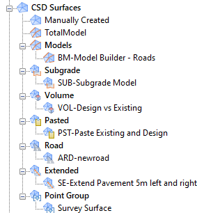
CSD Surface Source Collections
|
Surface Source Collection groups:
Manual input/creation
- These are as named by the user. This surface type is characterised
by the addition of 3D Faces, Breaklines, CAD Points and/or Point Files
in the Inputs tab of the Create/Edit Surface form
 Built Model/TotalModel
- Built models will be named with prefix BM- Built Model/TotalModel
- Built models will be named with prefix BM-
 Grading
- Grading String surfaces will be named with prefix
GR- Grading
- Grading String surfaces will be named with prefix
GR-
 Single String
- These are created from the Vertical Grading Editor and will be named
with prefix ARD- Single String
- These are created from the Vertical Grading Editor and will be named
with prefix ARD-
 Pasted
- These are created using the Paste Surfaces command and will be named
with prefix PST- Pasted
- These are created using the Paste Surfaces command and will be named
with prefix PST-
 Point Group
- These surfaces are created using COGO Points and Survey Strings.
Name of the surface will be as per the Point Group Point Group
- These surfaces are created using COGO Points and Survey Strings.
Name of the surface will be as per the Point Group
 Satellite
- These surfaces are created using the Surface from Satellite
command and will be named with prefix SAT- Satellite
- These surfaces are created using the Surface from Satellite
command and will be named with prefix SAT-
 Subgrade
- These surfaces are created from the Subgrade Model Manager command
and will be named with prefix SUB- Subgrade
- These surfaces are created from the Subgrade Model Manager command
and will be named with prefix SUB-
 Surface Extend
- These surfaces are created from the Surface Extend command and will
be named with extension SE- Surface Extend
- These surfaces are created from the Surface Extend command and will
be named with extension SE-
|
|
CSD Surface
|
Right click commands:
|
Surface Manager
|
Click to open the Surface Manager form.
The Surface Manager is used to manage the inputs to a CSD Surface as well as the display in the drawing: contours, triangles, slopes, slope arrows, elevations and directions. |
|
Toggle On/Off Contours
|
Toggles on/off the display of the contours for the selected Surface |
| Toggle On/Off Triangles |
Toggles on/off the display of the triangles for the selected Surface |
| Add Water Drop |
Starts the Water Drop command. |
| Export surface |
Starts the Export Surface command |
| Export Boundary |
Creates a polyline boundary around the surface. |
| Delete Surface |
Deletes the selected Surface |
|
|
 Point Groups Collection Point Groups Collection
|
Right click commands:
|
Point Groups
|
Point groups provide filtered lists of points that can be used to manage display and create surfaces
Click to open the Point Groups form. |
|
Create Survey Strings
|
Survey Strings connect like points in a Point Group (points that have the same description and, optionally, String number) together with 2D and/or 3D polylines, and can be applied as breaklines to a surface.
Click to Create Survey Strings.
If already created, this command allows editing of the survey string group behaviour. |
| Delete Survey Strings |
Deletes all Survey Strings added to a Point Group.
Click to Delete Survey Strings. |
| Survey String Manager |
Opens a dedicated interface to select points and survey strings for editing.
Click to open the Survey String Manager form. |
| Update Survey Strings |
Forces an update to survey strings. Click to Update Survey Strings. |
| Code Report |
Reviews the Codes (descriptions) of Cogo points in the drawing and compares to the Point Code Set and Survey String Set table.
Click to open the Code Report form. |
| Update Cogo Points |
Forces an update to cogo points. Click to Update Cogo Points. |
| Replace Codes |
Enables bulk replacement of Point Codes in the drawing. Click to start the Replace Codes command. |
| Compare Report |
Generate comparison reports between points, surfaces, alignments and polylines.
Click to run the Compare Report command. |
| Point Inquiry |
Starts the Point Inquiry command. Obtain information comparing two points. |
| Create Table |
Generate point and survey string tables. An example would be a legend table for created points.
Click to start the Create Group Table command. |
Manage Point Group Settings
[Civil 3D only] |
Manages how breaklines are added to the surface from Stringer.
Click to open the Manage Point Group Settings form. |
Civil 3D Point Group Link
[Civil 3D only] |
Link to Civil 3D point groups to enable management of the Civil 3D point geometry.
Click to open the Civil 3D Point Group Link form. |
Update C3D Cogo Point UDP
[Civil 3D only] |
Civil 3D can store additional point properties from Stringer, by creating and applying a User Defined Property Classification.
Click Update C3D Cogo Point UDP to create as well as update User Defined Properties. |
|
|
Point Group
 Point Group [Civil 3D Linked] Point Group [Civil 3D Linked]
|
Right click commands:
|
Point List
|
Click to open the Point List of all points in the Point Group. |
| Apply Styles from Code Set |
Click Apply Styles from Code Set to change the applied Point Style for every point in the point group based on the point descriptions, to match with the Point Code Set selected. This is useful when the Point Code is changed and it is desired to change the display of the point and/or the stored point properties.
Note: In Civil 3D, this command will not alter the point display - this is managed by Civil 3D Point Styles. |
|
|
 Points Collection Points Collection
|
Right click commands:
|
Code Editor
|
Click to open the Point Code Editor.
Enables editing of multiple point codes, string numbers and parameters. |
| Update Cogo Points |
Forces an update to cogo points. Click to Update Cogo Points. |
|
|
Points
|
Right click commands:
|
Edit Cogo Point
|
Edit the currently selected Cogo Point. Click Edit Cogo Point. |
| Select COGO Point |
Selects the point in the drawing |
| Zoom To |
Click to zoom to the Cogo Point in the drawing. |
|
Edit Cogo Point Table
|
Opens the attribute data table for the points |
|
Edit Survey String Table
|
Opens the attribute data table for the strings |
|
Edit Cogo Point Elevation
|
Opens a form to chagne the point elevation |
|
Edit Cogo Point Code |
Opens a form to change the point description (code) |
|
|
Survey Strings Collection
|
Right click commands:
|
Create Survey Strings
|
Survey Strings connect like points in a Point Group (points that have the same description and, optionally, String number) together with 2D and/or 3D polylines, and can be applied as breaklines to a surface.
Click to Create Survey Strings.
If already created, this command allows editing of the survey string group behaviour. |
| Survey String Manager |
Opens a dedicated interface to select points and survey strings for editing.
Click to open the Survey String Manager form. |
| Update Survey Strings |
Forces an update to survey strings. Click to Update Survey Strings. |
| Update Cogo Points |
Forces an update to cogo points. Click to Update Cogo Points. |
| Code Editor |
Click to open the Point Code Editor.
Enables editing of multiple point codes, string numbers and parameters. |
|
|
Survey Strings
|
Right click commands:
|
Survey String Manager
|
Opens a dedicated interface to select points and survey strings for editing.
Click to open the Survey String Manager form. |
| Update Survey Strings |
Forces an update to survey strings. Click to Update Survey Strings. |
| Update Cogo Points |
Forces an update to cogo points. Click to Update Cogo Points. |
| Code Editor |
Click to open the Point Code Editor.
Enables editing of multiple point codes, string numbers and parameters. |
| Split by Distance |
Splits Survey Strings for string segments longer than a user input value. Click to Split by Distance. |
| Zoom To |
Click to zoom to the start of the Survey String in the drawing. |
|
|
 Models Collection Models Collection
|
Right click commands:
|
Model Builder
|
Create models by including String Codes, to create Surfaces.
Click to start the Model Builder command. |
|
Toggle Display
|
Opens a form to quickly manage display of triangles and contours for created surfaces.
Click to open the Toggle Display form. |
|
Rebuild all Models
|
Rebuild all Models and update CSD Surfaces. Run this command after editing design Strings if additional CSD Models (excepting TotalModel) have been created.
Click to update all CSD Models. |
|
Surface Extend Models
|
The String Code Surface Extend command is used to create a Surface model related to a selected String, extending outwards from Code/s on that string.
Opens the Surface Extend Models form. |
|
Add High/Low Points
|
Adds points in the model to
represent high/low poitn locations. Click to open
Add
High/Low Points. |
|
Model Viewer
|
Click to open Model Viewer. |
|
Export KML
|
Export the model linework to KML and open in Google Earth. Click to start the Export KML command. |
|
Export Model
|
Export the model linework to various outputs. Click to start the Export Surface command. |
|
Export IFC 4x3
|
Export the model to IFC 4x3. Click to start the Export to IFC command. |
|
Feature Lines From Codes [Civil 3D Only]
|
Select any CSD Model and extract as Feature Lines in the drawing.
Click to start the Feature Lines from Codes command. |
|
|
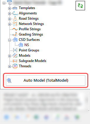
TotalModel
|
This is a special case Model that describes the model created using all Road and Network Strings.
Right click commands:
|
Edit Model
|
This is disabled for TotalModel. Users can create a new Model that links to TotalModel to make edits to the Model. |
| Rebuild Model |
Click to rebuild (update) the model and associated Surface/s.
Note: TotalModel automatically updates when Road or Network Strings are edited, unless rebuild is disabled.
|
|
Export Model
|
Export the model linework to various outputs. Click to start the Export Surface command. |
| Delete Model |
This is disabled for TotalModel. |
|
|
Model
|
Right click commands:
|
Edit Model
|
Edit the currently selected Model - this will open Model Builder into editing mode for the selected Model |
| Rebuild Model |
Click to rebuild (update) the model and associated Surface/s. |
|
Export Model
|
Export the model linework to various outputs. Click to start the Export Surface command. |
| Delete Model |
Deletes the currently selected Model.
Note: The associated Surface will also be deleted in this action.
|
|
|
 Surface Extend Collection Surface Extend Collection
|
No right click actions available for this collection
|
|
Surface Extend
|
| Rebuild Model |
Click to rebuild (update) the model and associated Surface/s. |
| Surface Extend Models |
The String Code Surface Extend command is used to create a Surface model related to a selected String, extending outwards from Code/s on that string. This form can also be used to edit inputs used to create surface extend models.
Opens the Surface Extend Models form. |
|
|
 Subgrade Models Collection Subgrade Models Collection
|
Right click commands:
| Subgrade Model Manager |
Opens the Subgrade Model Manager form. |
| Create Subgrade Model |
Create a subgrade model and Surface using a selected Design model.
Starts the Create Subgrade Surface command. |
| Output Subgrade Polylines |
Creates polylines for a selected subgrade model. Starts the Subgrade Polylines command. |
| Rebuild Subgrade Models |
Click to rebuild all created Subgrade Models |
|
|
Subgrade Model
|
|
Edit Subgrade Model
|
Edit the currently selected Subgrade Model - this will open Subgrade Model Manager into editing mode for the selected Model |
| Rebuild Subgrade Models |
Click to rebuild (update) the Subgrade Model and associated Surface/s. |
|
|
 Corridor Models Collection Corridor Models Collection
|
[Civil 3D only]
Right click commands:
|
Create Corridor
|
Creates a Civil 3D Corridor from a CSD Model. Once created, the updating of the corridor from Civil Site Design to Civil 3D can be managed.
Click to start the Create Corridor command.
Note: If the Corridor is removed from the Toolspace, it will not be deleted in the drawing. It will however be detached from Civil Site Design - Civil Site Design will no longer be able to update/rebuild the Corridor.
|
| Manage Corridors |
Enables recreation of a Corridor with adjusted input settings, as well as deletion of a Corridor and managing synchronization.
Click to start the Manage Corridors command. |
| Sync Corridors |
Corridors listed in the Corridor Models collection can be rebuilt with design changes from Civil Site Design.
Click to run the synchronization (rebuild) of all Corridors in the Corridor Models collection using the design information from Civil Site Design.
See Sync Corridors for more information. |
| Exchange Settings |
Establishes the Civil 3D Subassemblies to use in the creation of Assemblies, and the inputs that are controlled by Civil Site Design (such as the width and slope to a Code)
Click to start the Exchange Settings command. |
| Corridor Creation Settings |
Manages how targeting, parameter overrides and styles are applied.
Click to start the Corridor Settings command. |
|
|
Corridor Model
|
[Civil 3D only]
Right click commands:
| Sync Corridors |
Click to run the synchronization (rebuild) of the selected Corridor, using the design information from Civil Site Design.
See Sync Corridors for more information. |
| Manage Corridors |
Enables recreation of a Corridor with adjusted input settings, as well as deletion of a Corridor and managing synchronization.
Click to start the Manage Corridors command. |
|
|
 Threads Collection Threads Collection
|
Right click commands:
|
Thread Editor
|
Creates a Civil 3D Corridor from a CSD Model. Once created, the updating of the corridor from Civil Site Design to Civil 3D can be managed.
Click to start the Create Corridor command.
Note: If the Corridor is removed from the Toolspace, it will not be deleted in the drawing. It will however be detached from Civil Site Design - Civil Site Design will no longer be able to update/rebuild the Corridor.
|
|
|
Thread
|
Double click to run a Thread.
Right click commands:
| Run Thread |
Click to run the synchronization (rebuild) of the selected Corridor, using the design information from Civil Site Design.
See Sync Corridors for more information. |
| Edit Thread |
Enables recreation of a Corridor with adjusted input settings, as well as deletion of a Corridor and managing synchronization.
Click to start the Manage Corridors command. |
|
|
Hover Text Panel
|
Displays information text as each Object Collection or Object is hovered over
|
|
|
|
|
Project Assist
|
AI driven String and model design.
Click to start the Project Assist command.
|
|
Surface Tools
|
List of surface related commands.
|
Toggle Display
|
Manage display of triangles and contours for created surfaces.
Click to open the Toggle Display form. |
|
CAD Output
|
Create CAD entities of surfaces and models. Click to open the CAD Output form. |
|
Drawing Cleanup
|
Starts the Drawing Cleanup command. |
|
CAD Surface Drape
|
Drape objects onto a surface.
Click CAD Surface
Drape. |
|
Enquire
|
Obtain information for objects located near a selected location in the drawing. Click Enquire. |
|
|
Point Tools
|
List of Cogo Point commands.
|
Import Cogo Points
|
Use a file to import coordinated point geometry (Cogo) into the drawing. Click Import Cogo Points. |
|
Create Cogo Points
|
Create Cogo Points in the drawing. |
| Create by Reference |
Create points that have a dynamic reference (horizontal and/or vertical) to other objects. Click Create by Reference. |
| Create by Polyline |
Creates points along a polyline. Click Create by Polyline. |
| Create on Grid |
Creates points in a gridded pattern in the drawing. Click Create on Grid. |
| Convert Objects to Cogo |
Convert 2D and 3D objects in the drawing (Text, Mtext, Points and Blocks) into Cogo points. Click Convert Objects to Cogo. |
|
|
Excel Exchange
|
List of Excel exchange commands.
|
Excel Export
|
Create Excel export files from the design. Click Excel Export. |
| Excel Link |
Use Excel spreadsheet/s to control the design. Click Excel Link. |
| Sync Links |
Update the design using linked Excel files. Click Sync Links. |
|
|
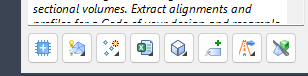
Volume Tools
|
|
Section Volume Report
|
Obtain section volumes for any created String. Click Sectional Volume Report. |
|
Section Volumes
|
Sectional volume reporting for design Strings (including subgrade). Starts the Section Volumes command. |
| Surface Section Volumes |
Obtain sectional volumes comparing any two surfaces, using the sections of a selected String. Starts the Surface Section Volumes command. |
|
Quick Section |
Generate quick sections along any polyline.
Click to start the Quick
Section command. |
|
|
Add Labels
|
Add plan labels in the drawing. Click Add Labels. |
|
Output Tools
|
List of output commands.
|
Plot Long Section
|
Create long sections for a selected String. Click Plot Long Section. |
| Plot Cross Section |
Create cross sections for a selected String. Click Plot Cross Sections. |
| Batch Plot to File |
Plot all layouts to file, such as pdf. Click Batch Plot to File. |
| Multi Setout |
Create Cogo Points (or text point display) describing Design Codes along Strings. Click Multi Setout. |
| Slope Patterns |
Create blocks to describe slope patters, scaled to fit between codes along a string. Click Slope Patterns. |
| Scale and Layout Settings |
Manage scaling of objects in viewports and set up default page settings for layouts. Click Scale and Layout Settings. |
|
|
Model Viewer
|
Click to start the Model Viewer command. |
|
Resources tab
|
The Resources tab includes help resources for new and existing users
|