Points by Polyline
Icon: |
Introduction
Creates Points at polyline vertices. Polylines can be selected individually or by layer.
Created points will have a description consisting of a Code (eg: LOT), including a Survey String number. Survey String numbers are auto incremented per polyline. If the Create Survey Strings command is run, the polyline will be recreated as a Survey String (enabling direct surface addition as a breakline and 3D polyline creation).
Horizontal Positioning
COGO Points are created at every vertex of the polyline/s selected.
COGO Points located at polyline vertices are dynamcally referenced to the polyline - editing the polyline and updating the points will result in the COGO point location changing to match the vertex.
Polyline Geometry, Point linework Paramters and Survey String Creation
For curved sections of the polyline, the software will insert a Curve Parameter code at the start of each curve, add a (statically positioned) mid-point COGO Point, and a Line Parameter code at the end of each curve.
If polylines are closed, the 'Close' point parameter will be added to one of the points, per polyline.
If the Create Survey Strings command is run, the Survey String will accurately describe the polyline coordinate geometry. Survey Strings can be created as 3D polylines and can act as direct breaklines to a surface via the Point Group.
Frontage and Rear Line Points
In the context of designing land parcels. Frontage points are those closest to a Road String and describe the points along the 'front' of a parcel. Rear points are those furthest from teh Road String and describe the points along the 'back' of a parcel.
This command allows users to associate the (dynamically reference) Frontage points to a Road String (or COGO Point, or 3D polyline) and the Rear points to be associated with (dynamically reference) the Frontage points. This would provide a convenient method for controlling grades from the back to the front of the parcel.
Elevation Positioning
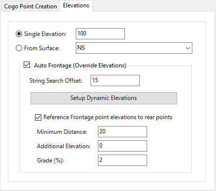
For elevations, users can:
-
Set a default elevation, either with a single elevation value or to obtain from the surface
-
Assign elevations for points close to a Road String (known as Frontage Points) as a dynamic reference to the Road String/Code. When enabled, the software will automatically scan the drawing for Road Strings within the offset specified, and also look for the nearest code on that road string (either left or right side, whichever is closest)
Note: Only Road type strings will be scanned for use as an elevation reference to points when Auto Frontage is applied. -
Assign elevations for points located more than a minimum distance away from the Frontage Points (known as Rear points) and with dynamic reference to the closest Frontage Point (measured olong the polyline).
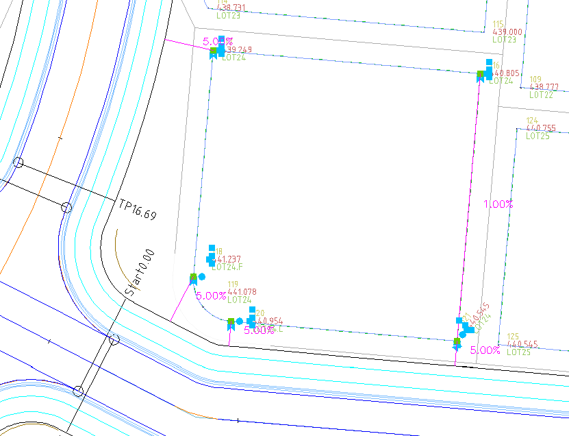
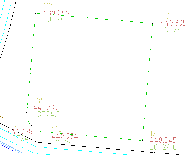
In the image above, the selected points are displaying their dynamic references (with purple lines and text). Points close to the Road have a dynamic 5% grade from the Road boundary code for elevation. Points far from the Road have a dynamic 1% grade to the Frontage Points.
Elevations from a Road String or Road String Code
When reference is made to a Road String or Road String Code, the software will locate the perpendicular distance along the Road String and then will report back the closest Sampled Section elevation along that Road. It is important to consider this - it may be required to add a Sampled Section on the Road at this location for the most accurate calculation.
In the Dynamic Positioning form, the software will report the calculated perpendicular chainage on the Road String, and the graphis when a point is selected will show a perpendicular line and any grade relationship established.
Details
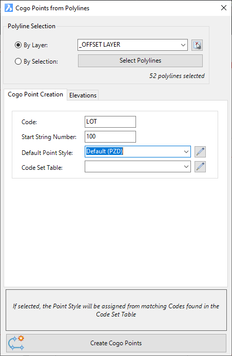
Upon selecting the command the following form is displayed:
|
|
|||||||||||||||||||||||||
|
Polyline Selection |
Select polylines to use for creating Points | ||||||||||||||||||||||||
|
By Layer |
Picklist of drawing layers to scan for polylines. Select the pick icon to pick an object in the drawing to set the layer. |
||||||||||||||||||||||||
|
By Selection |
If selected, click on Select Polylines and pick individual polylines in the drawing | ||||||||||||||||||||||||
|
|
The number of polylines will be displayed | ||||||||||||||||||||||||
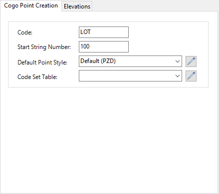
| Cogo Point Creation Tab | Set the controls for COGO points created | ||||||||||||||||||||||||
|
|
|
||||||||||||||||||||||||
| Cogo Point Creation Tab | Set the controls for COGO point elevations | ||||||||||||||||||||||||
|
|
|
||||||||||||||||||||||||
|
Create Cogo Points |
Click to create COGO points in the drawing | ||||||||||||||||||||||||