Active Drawing Settings
| Icon: |   |
Introduction
The Civil Site Design software requires the Designer to set how they want the software to perform for a particular drawing (design project). Many commands in Civil Site Design read information from the Active Drawing Settings form to undertake calculations and to control design and drafting outputs.
The Active Drawing Settings form includes multiple tabs for control over the settings governing the design inputs and outputs, including:
- The default surface to use for daylighting/batters on road elements created
- The controls for intersection connections
- Styles and settings for outputs of alignments, kerb returns, surfaces and more
- Management of layers and outputs.
The initial settings for this form are populated from the  Global Drawing
Settings - editing the global defaults will change the initial
local settings for future projects.
Global Drawing
Settings - editing the global defaults will change the initial
local settings for future projects.
| Notes: |
|
Icons
| Save and Exit | Saves any changes you have made to the settings and exits the Active Drawing Settigns Form | |
| Save As | Allows you to save your Active Drawing Settings as a Settings Template (.DEF) for importing into other projects | |
| Import Settings | Allows you to import Default Settings templates (.DEF) or any that you have saved previously | |
| Set Global Default Settings | Sets your current Active Drawing Settings as the Global Default Settings | |
| Create/Edit Templates | Opens the |
|
| Cancel | Exits the Active Drawing Settings without saving your changes | |
| Help | Opens this help file. |
Design Settings
The Design Settings tab of the Active Drawing Settings form is where you set your project defaults for Surfaces and Country of project.
Civil Site Design works by connecting kerb returns, cul-de-sacs and knuckles (horizontally and vertically) to particular point codes/labels that are created for each of the Roads. The software analyses levels/offset along cross section codes to determine which levels need to match to the kerb returns, cul-de-sacs and knuckles, and which levels define the edge of the through section on the main road at the intersection. In general terms, these codes should exist on each cross section of the road and for most subdivision purposes this will occur. If these codes are missing from the road cross sections, then the software will flag an error and you will need to check the labelling that has been used for the applied Template and fix the errors before continuing:
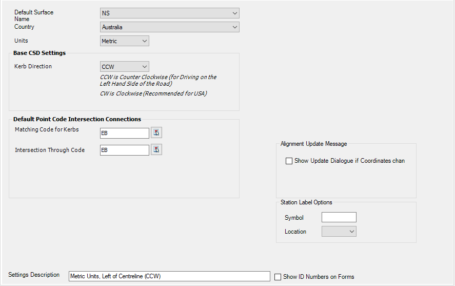
| Default Surface Name | The surface that Civil Site Design will reference for the current project, generally it will be your base or natural surface. |
| Country | Allows you to set what country you are currently working in, The default setting is Australia. (If the country you are after is not listed please contact Civil Survey Solutions) |
| Units | Sets the default Units for the project; Either Metric or Imperial |
| Base Settings | |
| Kerb Direction | Allows you to set the Kerb
Direction; Counter Clockwise (CCW) or Clockwise (CW) Note: Once the Kerb Direction is set and project data added, it Cannot be changed mid-way through. |
| Default Point Code Intersection Connections | |
| Matching Code for Kerbs | This sets the Code that the Kerb Return centrelines (and alignments) will match to |
| Intersection Through Code | This sets the Code on the Main Road
that is extended through the intersection zone - any Codes outside
of this are automatically excluded from the Auto Model build process
(where a Road network is built) in the zones where the kerb returns
are. Normally this is set to be the same as the Matching Code for Kerbs, however in the case of the kerb Code being matched to, say, the back of kerb, it may be required for the road sections to only show to the pavement edge. |
 Select Code from a
List Select Code from a
List |
Lists the available codes from the templates currently in the drawing. |
| Feet Options - THIS WILL ONLY DISPLAY IF THE UNITS ARE SET TO FEET | |
| Feet units are | Sets the feet units of the current drawing
(Not specified, Feet - International Feet, US Survey Feet This applies during XML Surface Import |
| For Export | Set whether to automatically use the
current drawing settings to manage the output scaling. Use
Settings or Always Prompt This applies during XML Surface Export |
| Station Label Options | |
| Symbol | Allows a symbol to be placed in the chainage/station text |
| Location | Set the position in the numeric text (hundreds or thousands) |
| Setting Description | Allows you to give brief details of the settings you have set, you might have separate settings for different types of project. |
| Show ID Numbers on Forms | Debug mode - identifies forms with a number for tracking |
Styles
The Styles section of the Active Drawing Settings allows you to define the Civil 3D styles for your design. You can select Alignment and label styles for Road, Kerb and Knuckle alignments, as well as Layer Prefixes. The C3D Styles Tab also let your define the style and layers for your Civil 3d Profiles.
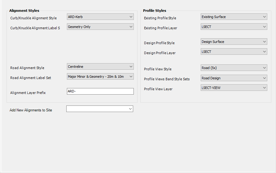
Use the pick lists to assign the Styles to use for display of different outputs as noted.
Kerb Details
The Kerb Details tab of the Active Drawing Settings is where you set your defaults for geometry, templates, sampling and grading of Kerb Returns.
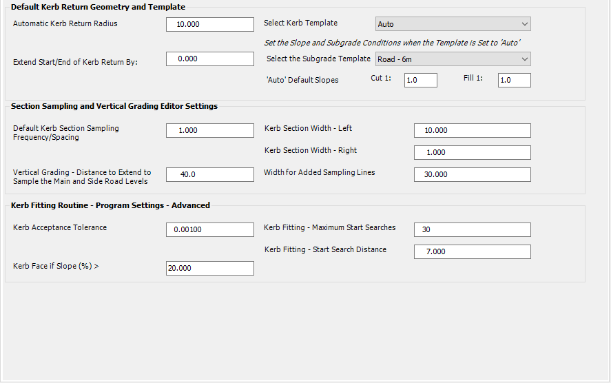
| Default Kerb Return Geometry and Template | |
| Automatic Kerb Return Radius | Default radius when running automatic kerb returns |
| Extend Start/End of Kerb Return by | Extends the start and end of kerb return by distance specified, maintaining the kerb radius. |
| Select Kerb Template | Selects the default kerb template. If Auto is selected, the kerb return cross sections will be constructed by finding matching codes on the Roads at the start/end of the kerb return alignment - linear transition to width and slope/height will be applied. |
| Select the Subgrade Template | Selects the default Subgrade Template to apply to kerb returns when Auto Template is selected |
| 'Auto' Default Slopes | Sets the default slopes applied to Kerb Returns when the Kerb Template is set to 'Auto' |
| Section Sampling and Vertical Grading Editor Settings | |
| Default Kerb Section Sampling Frequency | Sets the default section sampling along the kerb return |
| Vertical Grading - Distance to extend | When the kerb return is viewed in the Vertical Grading Editor, it will display the approaching and departing Road String Point Connection Code to this distance before and after the kerb alignment |
| Kerb Section Width (Left and Right) | The distance to section either side of kerb return alignment. |
| Width for Added Sampling Lines | The width of any extra sampling lines that are included along kerb return |
| Kerb Fitting Routine - Program Settings - Advanced | |
| Kerb Acceptance Tolerance | The kerb connection is iterative - this value sets the allowing misclose on the horizontal position |
| Kerb Face if Slope (%) > | If the slope of a section is greater than this value, the software will do a linear transition on the height difference instead of the slope |
| Kerb Fitting - Maximum Start Searches | Sets a start distance from the intersection to start searching for matching locations for the kerb returns |
| Kerb Fitting - Start Search Distance | Set the initial iteration distance to step along the two roads to find a kerb match location |
Road Details
The Road Details tab of the Active Drawing Settings is where you define the default settings for your Intersection Match-in, Section Sampling and Advanced Program Settings for your Road Design.
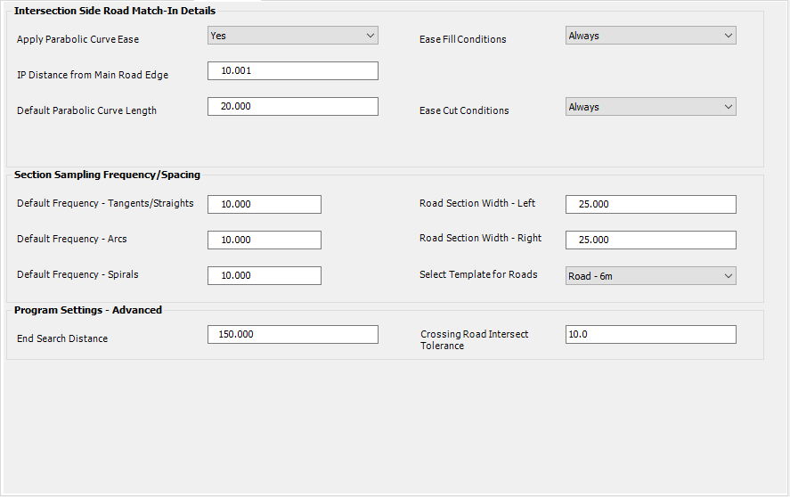
| Intersection Side Road Match-In Details | |
| Apply Parabolic Ease Curve | Applies parabolic ease curve on the side road vertical grade, at the time of creating a Road String |
| IP Distance from Main Road Edge | The distance you would like the automatic parabolic curve's IP to be placed, measured from the Point Connection Code on the main road |
| Default Parabolic Curve Length | The length of the automatic parabolic curve |
| Ease Cut/Fill Conditions | Set whether to Always provide a cut/fill ease curve, only in cut, only in fill, or never. |
| Section Sampling Frequency/Spacing | |
| Default Sampling Frequency (Tangents/Straights/Arcs/Spirals) | Defines how often you want to sample your road cross section along particular elements of an alignment |
| Road Section Width (Left/Right) | Width to sample from alignment |
| Select Template For Roads | Default Template to apply when a Road String is created - this can be edited at the time of creating the Road or when the Road is resampled. |
| Program Settings - Advanced | |
| End Search Distance | End search distance for intersections |
| Crossing Road Intersect Tolerance | Distance the program will search for possible crossing road intersections |
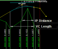
About Intersection Match-In - 'Vertical Curve Ease'
When side roads meet up with 'main' roads, the vertical grading of the side road is adjusted so it exactly matches the cross section of the main road where it crosses. Users are able to pre-set a vertical curve to be applied at the approach and/or departure of each intersection - we call this a vertical curve 'ease'.
 |
|
Vertical Grading Editor
The Vertical Grading Editor section of the Active Drawing Settings allows your to setup what you will see in the VGE window, as well as set the Design Aids for Vertical Alignments (Crest/Sag K Value, Max/Min Grade for Warning). You can also choose weather or not to update your Civil 3d Profiles when you exit the Vertical Grading Editor.
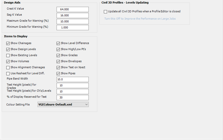
These settings are matched in the Display Settings button on the Vertical Grading Editor, with the following exceptions:
- Colour Setting File - sets the colours to apply in the Vertical Grading Editor
- Update all 3D Profiles when a Vertical grading Editor is closed - all Civil 3D profiles get updated (if created using the Create/Update Profiles command in the software) when a VGE window is closed.
Modelling
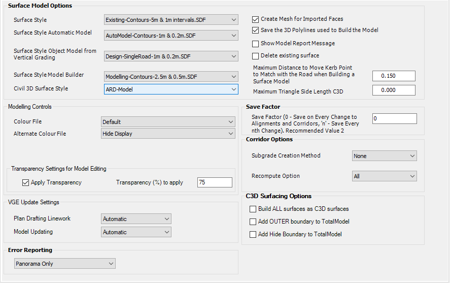
The Modelling Section of the Active Drawing Settings is where you define the settings for surface creation in Civil Site Design.
| Surface Modelling Options | |
| Surface Style | Pick the Surface Style to be applied when the software creates a single surface from all the road elements representing the road network. This is the default style if none of the below apply. |
| Surface Style Automatic Model | When the Auto Model command is run, the surface created will use this Surface Style |
| Surface Style Object Model from Vertical Grading | When a surface of a String is created from the Vertical Grading Editor, this Surface Style will be applied |
| Surface Style Model Builder | When a surface is created from Model Builder, this Surface Style will be applied. |
| Civil 3D Surface Style | When the software creates a Civil 3D surface for an existing Civil Site Design surface, this Civil 3D Surface Style will be applied |
| Create Mesh for Imported Faces | Tick this ON to create the alternate surface model at the time of building the Auto Model in Civil 3D. |
| Save the 3D Polylines Used to Build the Model | Tick
this ON if it is required for the breaklines to be
included in the drawing and for the surface to be dynamically
linked to these breaklines.
Tick this OFF to simply output the surface and store the breakline data in the surface definition. |
| Show Model Report Message | At
the time of building the surface model, the software creates additional
reports detailing the quality of the surface model created.
If it is desired NOT to receive a message that these files have been created then UNTICK this. |
| Delete Existing Surface | Delete the previous surface and create a new surface. Untick to just update the breaklines (takes longer in Civil 3D) |
| Maximum distance to move kerb point to match with the road when building a surface model | When kerb returns, cul-de-sac and knuckle alignments
do not meet tangentially to the Roads, there is overlap or a 'gap'
for the offset feature lines of the Road and the associated road
element.
This leads to a mismatch for the kerb offset points and the corresponding road points. Civil Site Design allows to a correction of the mismatch within the tolerance set here. When building the design surface model, it is important that matching coordinates have exactly the same value, otherwise there is the chance of having 2 points very close together that create minutely small triangles. Hence, before building the surface model, the software matches the coordinates at the ends of the kerb returns with the nearest point on the road at the point of tangency. If the distance is less than this ‘maximum distance’ value, then the coordinates on the kerb are adjusted to match to the road. Typical Imperial value 0.1 feet. Typical metric value 0.05 metres. Note: A report is printed showing all the matching points, the distance to the closest road point and whether or not the coordinates have been adjusted. |
| Maximum triangle side length | Applies a maximum triangle length control when building a surface - this setting does not apply to Civil 3D surface outputs. |
| Modelling Controls | |
| Colour File | Sets the default display colours used in the Build Models command |
| Alternate Colour File | Sets the secondary colours or hide display for any additional models |
| Transparency Setting for Model Editing | |
| Apply Transparency | Allows the user to see the workspace behind the Model editing form |
| Transparency (%) to Apply | Set the amount of transparency to apply. Default = 75% |
| Note: Transparency mode must be turned on in the drawing for this to take effect. | |
| VGE Update Settings | |
| Update settings | Allows the user to set whether the Plan Drafing Linework and Model Updating occurs automatically or manually. |
| Error Reporting | |
| Error Reporting | Use the pick list to set where Error Reports are presented |
| Save Factor | |
| Save Factor | Unused |
| Corridor Options - Not used | |
| Subgrade Creation Method | Not used |
| Recompute Options | Not used |
| C3D Surfacing Options | |
| C3D Surfacing Options | Users
can elect to completely skip the Quick Surface output and make
Civil 3D surfaces directly.
Note: If there are loops (overlaps) in the boundaries, then they will not be applied to the surface. The loop boundaries can have unexpected results in the output surface. |
Cross Section Usage
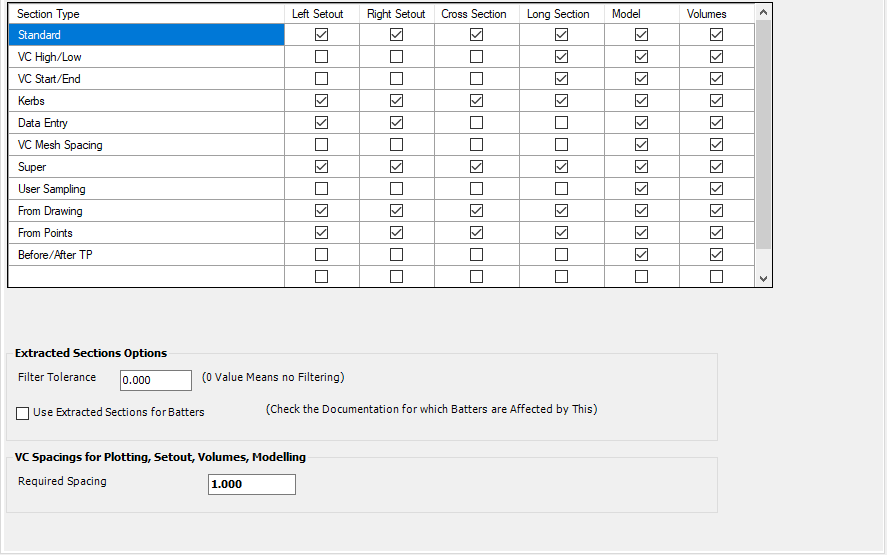
This is a matrix of the Type of Sampled Section and then the type of Output it should be included for.
List of Types and where they may be created:
| Sample Section Type | Command/Action Resulting in the Section |
| Standard | Standard section spacings defined at the time of Creating a Road, Kerb Return, Knuckle, Cul-de-sac or Roundabout |
| High/Low | Sections automatically added for the Design High/Low point/s - this is a result of the Vertical Design |
| VC Start/End | Sections automatically added for the start and end of Vertical Curves - this is a result of the Vertical Design |
| Kerbs | Sections added to Roads for the Start/End of kerb returns where they match to the edge of the Road |
| Data | Ability
to add Chainages set in the |
| VC Mesh | Allows additional sections to be automatically added for modelling or profile plotting through a vertical curve. The spacing can be set prior to plotting. |
| Super | Additional sections are added after application of Superelevation, to pick up the Super Points |
| Extra Spacings | At the time of creating a Road, the designer can change the spacings in a chainage range or add extra chainages |
| From Drawings | At the time of creating a Road, the design can read in lines on a selected layer to add extra sampling |
| From Points | Provided for future section creation option from point groups. Not currently used. |
| Before/After TP | Extra sections added very close to the Kerb match points, for improved grade calculations on the kerb returns. |
List of Outputs that the user can toggle on/off for the selected sampling group to be included:
| Output Type | Affected Command/s |
| Left Setout | affects setout of data left of the Centreline |
| Right Setout | affects setout of data right of the Centreline |
| Section | Cross Section Plotting |
| Profile | Long Secton Plotting |
| Model | Used in building models |
| Volumes | Used in Volumes |
| Extracted Sections Output | Controls section information |
| Filter Tolerance | Set a value to IGNORE breaklines that result in a level difference LESS than this value. This WILL EDIT THE SURFACE used |
| Use Extracted Sections for Batters | Pre-calculates the batters from the surface at the time of sampling. |
| VC Spacings | Set up tighter spacing for modelling of Vertical Curves |
| Required Spacing | Type in the required spacing |
Layer Names
The Layer Names section is where you decide what objects from Civil Site Design go on which layers in the drawing. You can assign layer name prefixes and modifiers.
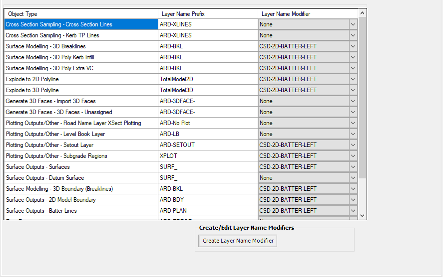
Details of the list is as follows:
Object Type Layer Name Prefix Layer Name Modifier See List, above Type in the desired prefix to the layer name Choose a particular Layer Name Modifier 'style' to append to the Layer Prefix using the Pick List. Designers create/edit the Layer Name Modifier 'style' sets by clicking on the Create Layer Name Modifier button:
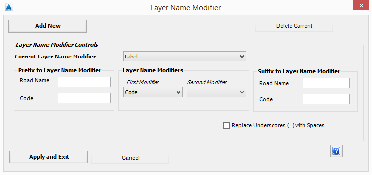
In the above Label Name Modifier style above, the resultant label name modifier would be -Road Name-Label.
Details of the form are as follows:
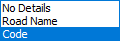
Add New Click on this button to create a new Label Name Modifier style. The designer will be prompted to name the style Delete Current Click on this button to delete the Current Label Name Modifier Modifier Controls - This set of commands enables the designer to append the Road Name and/or the Label to the Layer Name Prefix assigned to particular software drafting outputs Current Label Name Modifier Pick list to select the Label Name Modifier style to set current for editing or deleting The Label Name Modifier is made up of three components: Prefix to the Layer Name Modifiers, Layer Name Modifiers, and suffix to the Layer Name Modifiers Prefix to Modifiers - sets a prefix to each of the Layer Name Modifiers that can be assigned Road Name Type in a textual prefix for the Road Name modifier that may be assigned Code Type in a textual prefix for the Code modifier that can be assigned Layer Name Modifiers - provides the capacity to include Property information (Road Name or Label) to include with the Label Name First Modifier Use the pick list to assign either design properties as the first modifier in the label modifier text. List of options is as follows:
Leave blank for no assignment of information from the Road or Label propertiesSecond Modifier Use the pick list to assign either the Road Name (and/or Model Name) property or the Code property as the second modifier in the label modifier text. Selection options as above.
Leave blank for no assignment of information from the Road or Label propertiesSuffix to Modifiers - sets a suffix to each of the Layer Name Modifiers that can be assigned Road Name Type in a textual suffix for the Road Name modifier that may be assigned Code Type in a textual suffix for the Code modifier that can be assigned Replace Underscores (_) with Spaces Tick this ON for the software to replace any _ values to be spaces in the prefix or suffix modifiers. Apply and Exit Apply the changes and exit the form Cancel Exit without applying changes
About Layer Names - How they Work
The software uses AutoCAD lines and polylines as part of the output of data. In the tab where you set up layer names that the software uses for display of different design elements, users can set up the layer names required for different output types.
The Layer is made up of:
A Layer Prefix: this is a typed in name, and optionally:
A Layer Name Modifier: this appends to the Layer Prefix optionally with a combination of the Road Name and/or cross section Label (eg: LEB, LFPI, C.L.)
Linework outputted to the drawing is initially generated using the software fast-draw graphics (as blocks) - there is a command to generate polyline outputs from this. Unless controlled otherwise, this polyline outputted linework would be controlled from the Explode to 2D Polyline and Explode to 3D Polyline layer controls
Designers can set up their own Layer Name Modifier 'styles' and apply them as desired.
Miscellaneous
The Miscellaneous section of the Active Drawing Settings allows users to modify settings for Arrow type, size and angle. As well as Arc to Chord distance for mdelling purposes, as well as allowing either single or multiple variations for codes at a single cross section. Users can also specifiy what tangent check tolerance they want the program to use.
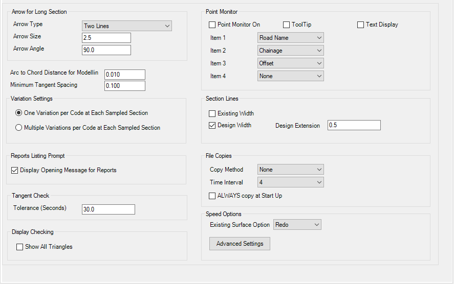
| Arrow for Long Section | |
| Arrow Type | Sets the arrow type to use on the long sections. Use the pick list to select the arrow head type rquired |
| Arrow Size | Sets the arrow size |
| Arrow Angle | Use the pick list to set the angle of the arrow |
| Arch to Chord Distance for Modelling | Sets the chord distance for display of vertical curves on Long Sections |
| Minimum Tangent Spacing | Sets the minimum spacing for display of tangents on Long Sections |
| Variation Settings | |
| Variation Settings | Users pick whether a Code can be modified by one Variation only, or if various Variations should make compounding edits on a Code |
| Reports Listing Prompt | |
| Display Opening Message for Reports | Untick to not display a confirmation message box before displaying reports |
| Tangent Check | |
| Tolerance (Seconds) | Set an angle tolerance that is acceptable for Tangency. This value is used when running the tangency check command. |
| Display Checking | |
| Show All Triangles | A 'debug' option to display all triangles - ignores any boundary and or edits applied to any surface. |
| Point Monitor | Special Notes: Does not apply to Civil
3D. Sets whether a tooltip is displayed in the drawing describing the position of the mouse cursor with respect to alignments in the drawing. Options: |
| Point Monitor On | Tick on to enable tooltip display |
| Tooltip | Tick on to display a dynamic tooltip next to the mouse cursor |
| Text Display | Tick on to display text in the bottom left corner |
| Item 1-4 | Pick what to display on the tooltip. Options: Road Name, Chainage, Offset, Label, None |
| Section Lines | Controls width of sampled section lines, if displayed |
| Existing Width | If ticked on, applies widths as per the Resample Cross Section command > Section Widths form |
| Design Width | If ticked on, displays lines to match the width of the design (LBAT to RBAT) plus a user defined Design Extension |
| File Copies | Allows for backup of the data folders |
| Copy Method |
|
| Time Interval | Number of times opening the data set before making a backup |
| ALWAYS copy at startup | When the data folder is first opened, a backup of the data is made. |
| Speed Options | Additional controls to manage the speed of calculations and what is calculated. |
| Existing Surface Option | Controls
whether sections are calculated 'on the fly' or saved to the data
folders.
Redo requires more processor speed, so may slow on larger jobs. |
| Advanced Settings | Opens
up advanced build controls.
By default, the software auto recalculates all Roads, Kerbs, other road network objects and surfaces. This can become slower in larger jobs. The Advanced Settings allows the user to knobble the automatic rebuild processes. All inputs and controls are as described in the |
CSD Styles
The CSD Styles section of the Active Drawing Settings allows you to define the styles for Alignments created by CSD. You can select Alignment styles sets for Road, Kerb and CulDeSacs and other alignments. There is also additional Annotation Controls for both plan and setout purposes.
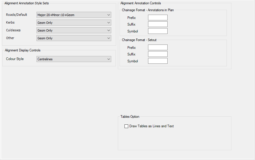
| Alignment Annotation Style Sets | Default label (annotation) style sets to apply to alignments upon creation |
| Roads/Default | Pick list of Annotation sets. Applied to road alignments |
| Kerbs | Pick list of annotation sets. Applied when the software creates kerb return alignments |
| Cul-de-sacs | Pick list of annotation sets. Applied when the software creates cul-de-sac alignments |
| Other | Pick list of annotation sets. Not used. |
| Alignment Display Controls | Pick an alignment display control style - this sets the layers to use for display of the alignment object - line, curve and spiral segments |
| Colour Style | Pick a colour style |
| Alignment Annotation Controls | Allows for additional labelling controls on alignments, as well as for setout |
| Chainage Format - Annotations in Plan | Allows a suffix, prefix or symbol text to be added to the annotation labels |
| Prefix | type in a prefix |
| Suffix | type in a suffix |
| Symbol | type in for a text symbol |
| Chainage Format - Setout | Allows a suffix, prefix or symbol text to be added to the setout labels |
| Prefix | type in a prefix |
| Suffix | type in a suffix |
| Symbol | type in for a text symbol |
| Tables Option | |
| Draw Tables as Lines and Text | Tick to draw a table as lines and text, or Unticked a Table will be inserted. |