Alignment Grid Editor
Icon: |
Introduction
Use this command to edit an Alignment in a Grid Format. This command can be used to change the Alignment geometry in the drawing. This form is modeless - users can freely move around and undertake AutoCAD commands in the drawing, with this form showing on screen.
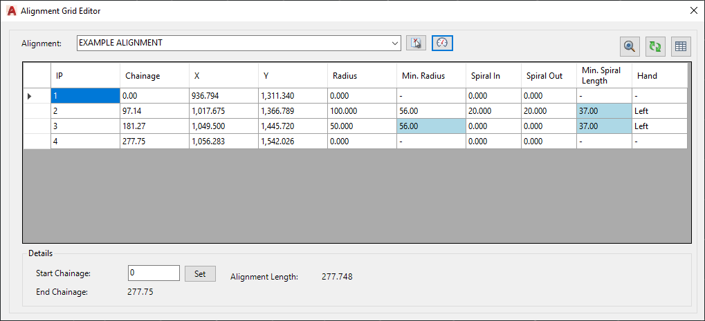
Once open, users can edit and zoom to different Alignments (using the dropdown or the picker button)as well as optionally set the Speed Table and Start Chainage/Station. The IP's (PVI's) are listed in the per row in the form with the curve and spiral attributes noted accross the columns. Once the Speed Table is set, the Minimum Radius and Spiral Lengths will be listed for any IP/PI with a Radius assigned and values that are below the minumum are highlighted.
Users can edit the following columns:
- Radius: a filleted Bend (Curve) is assigned to the two Straights (Tangents) that meet at the IP/PI you are editing. The Bend automatically maintains tangency and cannot overlap the chainage/station, Bend or Spiral extents of another IP/PI;
- Spiral (Length) In: Creates a Spiral on the lower chainage/station side of the IP/PI you are editing. The Spiral will automatically transition from the straight (tangent) portion of the Alignment into the Bend (curve) portion;
- Spiral (Length) Out: Creates a Spiral on the higher chainage/station side of the IP/PI you are editing. The Spiral will automatically transition from the Bend (curve) portion of the Alignment into the straight (tangent) portion.
User entries are detailed below.
Use the Windows Close button (x at the top right) to close the form.
Notes:
- After making a Grid entry or moving the Alignment via Grip or Edit Alignment form, click the Refresh button:

- Entries that cannot be solved will return to their original value.
Details
Upon selecting the command the following form is displayed:
|
|
|
|
Alignment (picklist) |
Select the alignment to edit. |
|
|
Click here to select the alignment to edit from the drawing. |
|
|
Opens the Speed Table form. Note: once Speeds are set, the Min, Radius and Min, Spiral Length will highlight design issues. |
|
|
Zooms to the highlight row (users must click on the cell in the first column to highlight the row). |
|
|
Update the alignment geometry details. |
|
|
Creates a table of the geometry as listed. Click in the drawing to position the table. |
|
[Alignment IP List] |
Table controlling the alignment IP/PI points |
|
> First Column |
Use this to select and highlight a row |
|
IP |
Displays the IP/PI numbers, in order of chainage/station |
|
Chainage |
Displays the chainage/station of the IP/PI (non editable) |
|
X |
Displays the X coordinate. |
|
Y |
Displays the Y coordinate. |
|
Radius |
Entry for the Curve Radius. |
|
Min. Radius |
Display for the Minimum Radius based on the assigned Speed Table. |
|
Spiral In |
Entry for the Length of the Spiral into the IP/PI's Curve. |
|
Spiral Out |
Entry for the Length of the Spiral out from the IP/PI's Curve. |
|
Min. Spiral Length |
Displays the Minimum Spiral Length as set by the assigned Speed Table. |
|
Hand |
Displays which side of the Alignment the Curve turns. |
|
Details |
Table controlling the Alignment IP/PI points. |
|
Start Chainage |
Entry for the Start Chainage/Station of the alignment. |
|
Set |
Click to set the Start Chainage/Station. |
|
End Chainage |
Displays the End Chainage/Station of the alignment. |
Refresh the form to update the values and the line work in the Plan View and Close the form when finished editing.