|
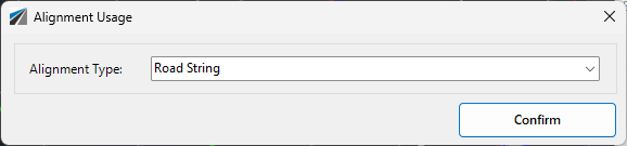
Road String
|
Select to create a Road String, treating the alignment as a Road Centreline. Process would be as per the Create/Edit Road form with sampling assumed from the Settings. |
|
Road edge connection or String control
|
Expands to two options in the Workflow:
- Associated with a Road. The alignment can be:
- Used to Control the edge of the road, including creating a string for vertical control.
- Treated as an independent string, with independent cross section sampling. Variations will be added to the Road string to remove codes outside of the Road Edge code. The start/end of the string will obtain elevations from the Road elevations (used the Road Edge code and the slope between the Road C.L. code and Road Edge code.
- Not Associated with a Road. A String will be created, able to be draped onto a surface for a start/end distance, and added to the Design Model
|
|
Footpath Control
|
Associated with a Road, this alignment can be used to edit the horizontal position and elevation of the designated footpath/sidewalk codes for the Road String. Alternately, it can be treated as an independent footpath/sidewalk string with independent cross section sampling. The corresponding footpath/sidewalk codes will be removed from the associated Road String and a model created. |
|
Sawcut Control
|
Associated with a Road, this alignment can be used to insert and control the offset and elevation of a code on the Road that represents a pavement saw cut. The addition of these alignments enable automatic inclusion to the Road as a 'Road Widening' project. |
|
Boundary Line
|
Associated with a Road, this alignment can be used to control the Boundary Code of the Road or the extents of the Road design (by editing the batter/daylight offset) |
|
Island or Roundabout String
|
These are not associated with a Road String.
Islands are draped onto the Design Model surface and added to the Design Model (with Islands) model.
Where one 'island' alignment is located internal to another 'island' alignment (such as a Roundabout), the software will drape the outer one onto the Design Model surface and apply an Auto Profile to the internal island as well as add Design Constraints. |
|
Existing (no design) Road CL control
|
Creates a Road String, with elevations matching the existing (sampled) surface.
If a Template is assigned, the Road Edge and Footpath/sidewalk Codes can be matched to the surface by including Existing Road Edge and Existing Footpath alignments.
If no Template is assigned, left and right Road Edge codes will be added with minimal offsets, to enable intersection match in. If Existing Road Edge control alignments are included, these will be used (via Variations) for offset control. |
|
Existing (no design) Road Edge control
|
Used to define the Road Edge of an existing road.
Where used without including an Existing (no design) Road CL Control, users can elect to treat this as a Road String, to enable kerb/curb returns to connect directly to the existing road edge.
Where used with an Existing (no design) Road CL control the alignment will automatically be applied as a Variation to the associated Existing (no design) Road CL control - a Match to Surface variation is applied automatically to the Road Edge code. |
|
Existing (no design) Road Footpath control
|
Used to define existing footpaths/sidewalks of an existing road.
Where used without including an Existing (no design) Road CL Control, this acts only as a draped string (string with elevations matching the existing surface) added to the Design Model.
Where used with an Existing (no design) Road CL control that has a Template applied that includes the Footpath Codes, the alignment will automatically be applied as a Variation to the associated Existing (no design) Road CL control - a Match to Surface variation is applied automatically to the Footpath code/s.
Note: Both inside edge and outside edge alignments can be created an applied as Footpath control alignments - the result is variations applied for both the inner and outer Footpath codes.
|
|
Nothing
|
The alignment should not be used. |