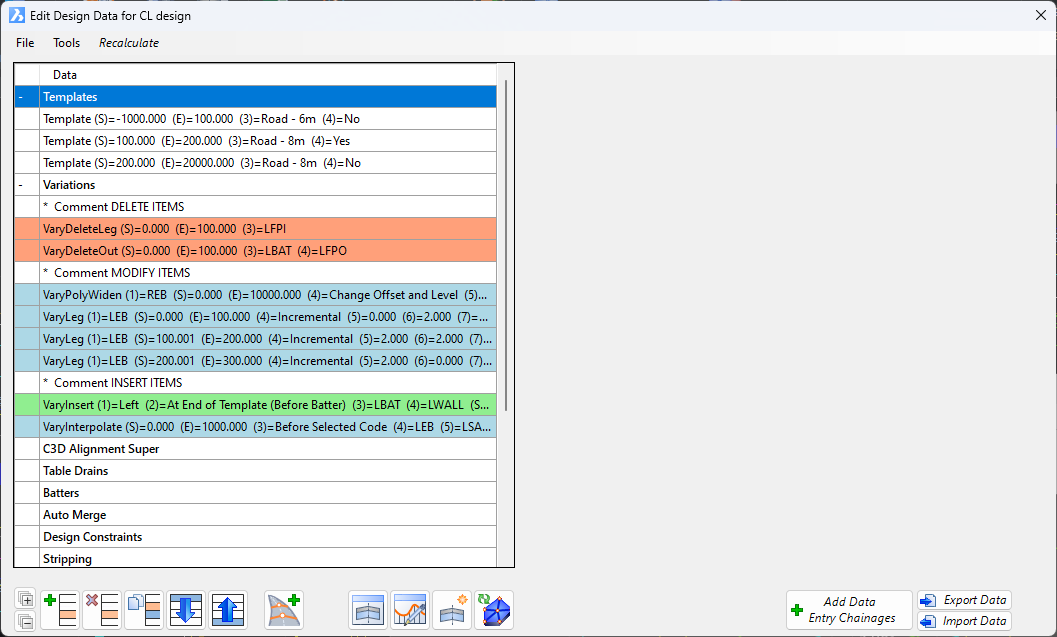
The Design Data form is accessible from multiple locations: the Design Data Form command on the Ribbon/Menu, as well as from command icons located on the Vertical Grading Editor and Cross Section Windows.
Overview
The Design Data Form facilitates editing of the cross sections, application of stripping and compaction factors for plotting, and the display of Design Constraints on the Vertical Grading Editor and Cross Section Windows.
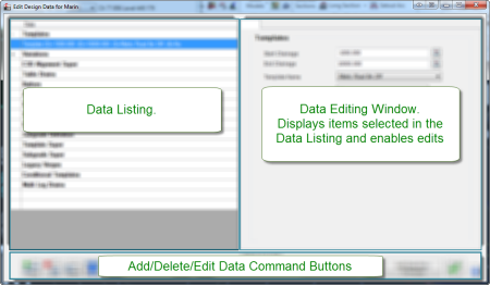
The Design Data Form consists of two data panels:
- Top Left: Data Summary and edit selection
- Top Right: editing of individual data entries
The lower section includes functional buttons to add, copy, reorder and save Data, as well as opening the Vertical Grading Editor or Cross Section Windows.
Data Listing and Data Entries:
- To expand a heading, click on the + sign next to the heading.
- To collapse a heading, click on the - sign next to the heading.
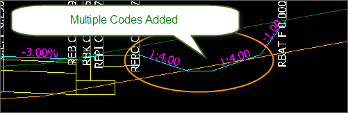
Variation Listing - coloured by variation type
The variations added will have a background colour applied based on whether
the variation applies an insert, edit or delete action (comment is uncoloured).
Terminology - Codes and Sections
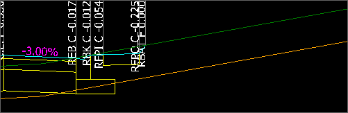
A Code is a defined design point on a cross section. It normally represents a grade break in the cross section top surface. Codes should be named with a prefix of L for left of centreline or R for right of centreline.
A Section is a cross section line that connects between two codes, and can include one or more subgrade layers represented by closed (or open ended) shapes. Sections are always measured perpendicular to the centreline alignment.
Notes When Adding Data
Start and End Chainage
When data is added to the cross sections between a start and end chainage, calculations for the cross section are made at every SAMPLED section along the CSD Object. If a start chainage was set to, say 22.5, and the sampling was every 10 metres, then the first cross sections where this data would apply would be at Chainage 30.
Almost every data entry allows the user to select the option to Create Chainage at start and/or end. Using this option will enable the addition of sampling directly from the Start Chainage and End Chainage of the Data Entry. The button Add Data Entry Changes must be used to add these extra sampled sections.
Double Click to Add New Data Entries
Double clicking on a Data heading will result in a new entry being added for
that Data type.
Details
This is the central data storage location to fully control the cross sections applied to the road object. The main components of the software are noted below:
Data Listing Commands
Data is added by selecting the Data type in the list and clicking on the Add Entry button. Data Input Options to control the cross sections are listed below:
|
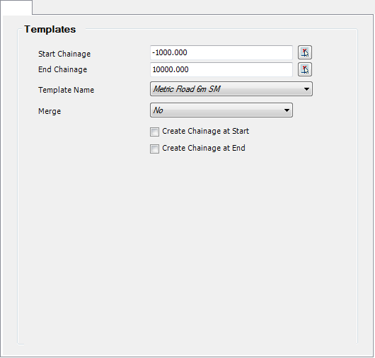
Templates |
Templates are 'typical cross sections' that can be applied to a road - they are a collection of sections/codes comprising a total cross section, inclusive of subgrade data and batter conditions. Templates can be created and edited via the  Create/Edit Templates command - accessing the Template Editor is also available from the Vertical Grading Editor. Create/Edit Templates command - accessing the Template Editor is also available from the Vertical Grading Editor.
The Data Editing Window appears as follows:
|
| Start Chainage |
Select the Start Chainage from which the entry should apply. Type or use the pick list to select from the drawing. |
| End Chainage |
Select the End Chainage at which the entry should stop applying. Type or use the pick list to select from the drawing. |
| Template Name |
Select the cross section Template to apply |
| Merge |
Select Yes to merge from the previous Template at the Start Chainage to the selected Template at the End Chainage. Merging will occur linearly over the start and end chainage ranges on the basis that the Code names match and both templates have the elevation specified by the same method (either by level difference or slope). |
| Create Chainage at Start |
Store the Start Chainage in this form to be added as a Sampled Section on the current CSD object (see above for more details) |
| Create Chainage at End |
Store the End Chainage in this form to be added as a Sampled Section on the current CSD object (see above for more details) |
Notes:
The template list is always sorted by the starting chainage. If you inadvertently specify templates with overlapping ranges, the first template, sorted by starting chainage, is used.
At least 3 Template entries are required to initiate a Template merge. 1st template entry leads up to the transition zone (Template 1). 2nd template entry spans the template merge zone - the exiting Template is to be specified (Template 2) AND Merge must be ticked ON. 3rd template entry starts from the end of the Template merge entry (Template 2).
|
| Variations |
Variations provide a range of tools for altering the cross section, normally on a section by section (code by code) basis, without creating a new Template or editing a Template. Variations are an edit to the cross section, and are applied in order in the data listing. Multiple edits on a code is able to be applied via a sequence of variations on that code.
Variations that edit a cross section Code typically work from the inside (closest to the Road CL) out - when a Code of the cross section is adjusted, the Code/s working outward from the adjusted Code have their position changed (offset and level) to maintain their relative position to the adjusted Code. When applying any alignment control, remember to work from the inside edge (closest to the Road CL) you want adjusted.
When a Variation is to be added, a form will display listing the available variations. Select a Variation from the list, then select the Insert Position. This can be set in the Variations list as follows:
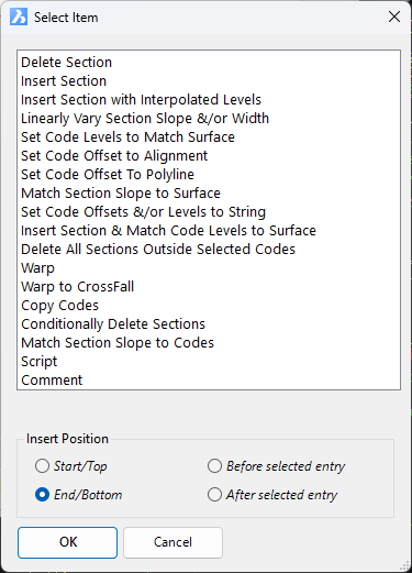
- Start/Top: top of list
- End/Bottom: end of list
- Before Selected Entry: above the Variation entry you had highlighted at the time of clicking Add Entry
- After Select Entry: below the Variation entry you had highlighted at the time of clicking Add Entry
Note: Variations do not apply to the Batter codes (LBAT or RBAT) or Table Drains Codes - Batter overrides should be used in these cases.
Each Variation is listed, below:
|
|
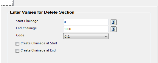
Delete Section |
This command will delete a selected leg (Code) from the cross section. The next outer Code and section will move inward to connect with the previous Code.
|
| Start Chainage |
Select the Start Chainage from which the entry should apply. Type or use the pick list to select from the drawing. |
| End Chainage |
Select the End Chainage at which the entry should stop applying. Type or use the pick list to select from the drawing. |
| Code |
Select the Code to delete |
| Create Chainage at Start |
Store the Start Chainage in this form to be added as a Sampled Section on the current CSD object (see above for more details) |
| Create Chainage at End |
Store the End Chainage in this form to be added as a Sampled Section on the current CSD object (see above for more details) |
|
|
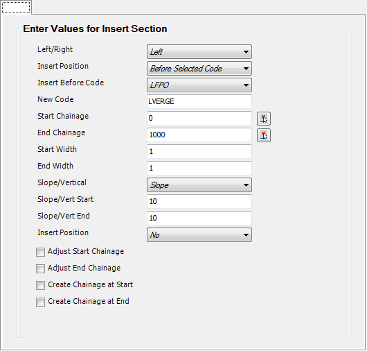
Insert Section |
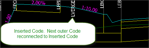
This command will insert a new Code and Section onto the cross section. The next outer Code and section will move outward and connect with the new Code.
Note: Inserting a Code relocates the next outer Code to reconnect to the NEW Code (and therefore the rest of the cross section, working outwards from the inserted Code).
|
| Left/Right |
Select to insert a new Code Left of the centreline or Right of the centreline |
| Insert Position |
Select Before Select Code or At End of Template (before Batters) |
|
|
Before: Insert before Insert Before Code (specified on the next line) |
|
|
At End: Inserts at the end of the cross section, BEFORE the batters or Table Drains |
| Insert Before Code |
Use the pick list to select the Code to insert before (inwards toward the centreline) |
| New Code |
Enter the name of the new Code. Make sure that it starts with L if it is on the left or R if it is on the right. |
| Start Chainage: |
Select the Start Chainage from which the entry should apply. Type or use the pick list to select from the drawing. |
| End Chainage: |
Select the End Chainage at which the entry should stop applying. Type or use the pick list to select from the drawing. |
| Start Width: |
Enter the width required for the new template Section at the starting Chainage |
| End Width: |
Enter the width required for the new template Section at the ending Chainage
Note: The program linearly interpolates in-between the Start and End Chainages |
| Slope/Vertical: |
Use the pick list to select if the elevation for the Code is calculated by slope or vertical distance. |
| Slope/Vert Start: |
Enter the value at the start chainage |
| Slope/Vert End: |
Enter value at the end chainage
Note: The program linearly interpolates in-between the Start and End Chainages |
| Plot Flag: |
Select Yes to include the Code offset/level information in the Data Bands when plotting cross sections. Select No to not Code this Code on the cross sections |
| Adjust Start Chainage: |
Applies the Inserted Code over the selected chainage range, except not at the exact Start Chainage specified. |
| Adjust End Chainage: |
Applies the Inserted Code over the selected chainage range, except not at the exact End Chainage specified. |
| Create Chainage at START |
Store the Start Chainage in this form to be added as a Sampled Section on the current CSD object (see above for more details) |
| Create Chainage at END |
Store the EndChainage in this form to be added as a Sampled Section on the current CSD object (see above for more details) |
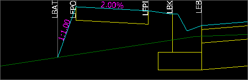
Example:
| Before |
After |
 |
 |
|
|
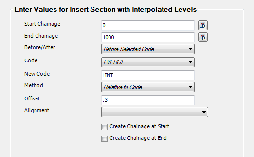
Insert Section with Interpolated Levels |
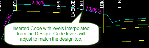
This command will insert a new Code in the cross section, with the Code adopting the top surface levels of the cross section (not forming a grade break). This is a very useful tool for adjusting the subgrade behaviour and not adjusting the design grade breaks.
Special Note: This Variation cannot be used in conjunction with other variations - unexpected results will occur when compounding variations are applied
|
| Start Chainage: |
Select the Start Chainage from which the entry should apply. Type or use the pick list to select from the drawing. |
| End Chainage: |
Select the End Chainage at which the entry should stop applying. Type or use the pick list to select from the drawing. |
| Before/After |
Select to insert before the selected reference Code or after. Before will insert the code in the section closer to the centreline, with After inserting the code in the section further from the centreline. |
| Code |
Pick the reference Code. This sets the section where the New Code is to be inserted and can be used as a reference for offset location of the New Code/ |
| New Code |
Name for New Code being inserted. |
| Method |
This establishes the method to use for determining the offset location of the New Code on the cross section. Options are:
- Relative to Code: Set an offset measured from the selected Code
- Fixed Distance: Set an offset measured from the centreline of the current CSD object
- Use Alignment: Pick an alignment to define the offset location
Note: the New Code must be located in the Section immediately before or after the Code selected.
|
| Offset |
If Method is set to Relative to Code, this would be an offset distance measured from the Code selected
If Method is set to Fixed Distance, this would be the distance measured from the centreline |
| Alignment |
If Method is stet to Use Alignment, use this pick list to select an alignment from which to establish the offset location of the New Code. |
| Create Chainage at START |
Store the Start Chainage in this form to be added as a Sampled Section on the current CSD object (see above for more details) |
| Create Chainage at END |
Store the End Chainage in this form to be added as a Sampled Section on the current CSD object (see above for more details) |
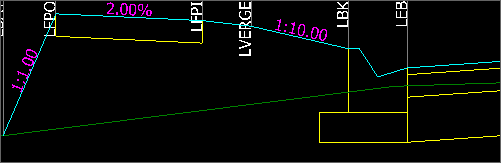
Example:
| Before |
After |
 |
 |
|
|
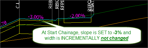
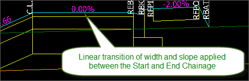
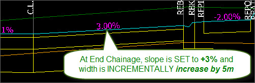
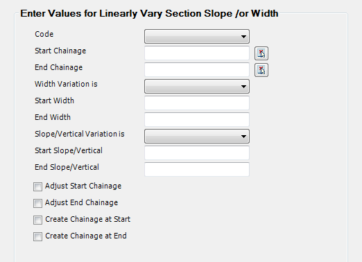
Linearly Vary Section Width &/or Slope |
This command can be used to linearly adjust the width and/or slope of a Section in the cross section, over a specified chainage range.
|
| Code |
Select the Code to adjust |
| Start Chainage: |
Select the Start Chainage from which the entry should apply. Type or use the pick list to select from the drawing. |
| End Chainage: |
Select the End Chainage at which the entry should stop applying. Type or use the pick list to select from the drawing. |
| Width Variation Is |
Select either Set or Incremental:
- Set: Users type in exact widths required for the Section.
- Incremental: Users type in a CHANGE in the current width (+ to increase and - to decrease)
|
| Start Width: |
Enter the width required at the Start chainage |
| End Width: |
Enter the width required at the End chainage |
| Slope/Vertical Variation Is |
Select either Set or Incremental:
- Set: Users type in exact slope required for the Section.
- Incremental: Users type in a CHANGE in the current slope/vertical distance (+ to increase and - to decrease)
Note: the section elevation is either defined by a slope or a vertical difference relationship. This is defined at the time of creating a Code.
|
| Start Slope/Vertical |
Enter the value at the start chainage |
| End Slope/Vertical |
Enter the value at the end chainage |
| Adjust Start Chainage:: |
Applies the change over the selected chainage range, except not at the exact Start Chainage specified. |
| Adjust End Chainage: |
Applies the change over the selected chainage range, except not at the exact End Chainage specified. |
| Create Chainage at START |
Store the Start Chainage in this form to be added as a Sampled Section on the current CSD object (see above for more details) |
| Create Chainage at END |
Store the End Chainage in this form to be added as a Sampled Section on the current CSD object (see above for more details) |
Example:
|
|
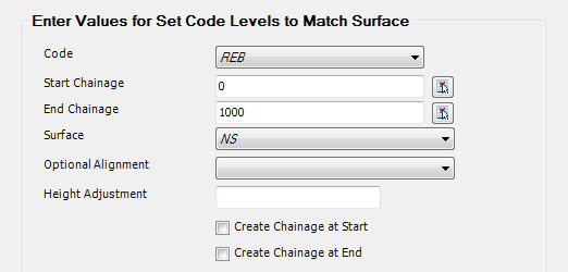
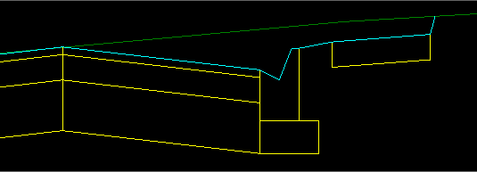
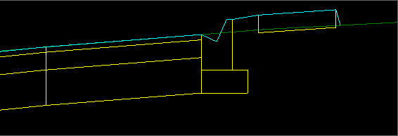
Set Code Levels to Match Surface |
This command can be used to set a Code to adopt a surface level and optionally an alignment offset.
|
| Code |
Select the Code to adjust |
| Start Chainage: |
Select the Start Chainage from which the entry should apply. Type or use the pick list to select from the drawing. |
| End Chainage: |
Select the End Chainage at which the entry should stop applying. Type or use the pick list to select from the drawing. |
| Surface |
Select the surface to match the code to |
| Optional Alignment |
Select the Alignment to use as the Code offset if required |
| Height Adjustment |
This gives an option to add of subtract from the calculated level, useful for adding seal overlay to existing road. |
| Create Chainage at START |
Store the Start Chainage in this form to be added as a Sampled Section on the current CSD object (see above for more details) |
| Create Chainage at END |
Store the End Chainage in this form to be added as a Sampled Section on the current CSD object (see above for more details) |
Example:
| Before |
After |
 |
 |
|
|
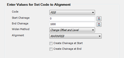
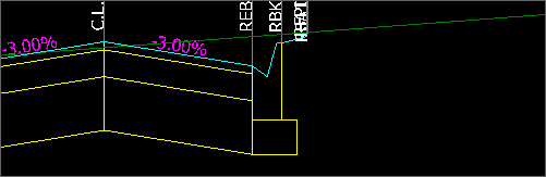
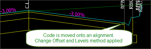
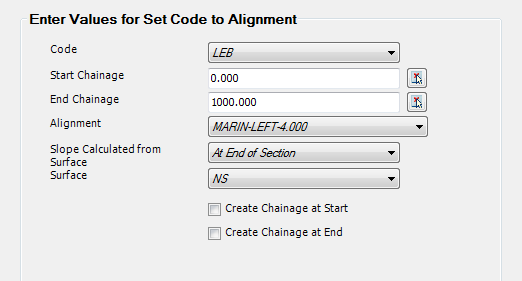
Set Code Offset to Alignment |
This command can be used to set a Code to adopt offset of an alignment and maintain either the slopes or the level difference of the Section.
|
| Code |
Select the Code to adjust |
| Start Chainage: |
Select the Start Chainage from which the entry should apply. Type or use the pick list to select from the drawing. |
| End Chainage: |
Select the End Chainage at which the entry should stop applying. Type or use the pick list to select from the drawing. |
| Widen Method |
When the Code offset is adjusted to match the alignment, options for establishing the elevation of the code is optionally controlled by:
- Change Offset and Level: as the Code offset changes, the elevation of the Code is adjusted to maintain the current Section slope
- Change Offset - Keep Level: as the Code offset changes, the elevation of the Code is not adjusted (the relative height difference across the Section is maintained).
|
| Alignment |
Select the Alignment to use as the Code offset |
| Create Chainage at START |
Store the Start Chainage in this form to be added as a Sampled Section on the current CSD object (see above for more details) |
| Create Chainage at END |
Store the End Chainage in this form to be added as a Sampled Section on the current CSD object (see above for more details) |
Example:
| Before |
After |
 |
 |
|
|
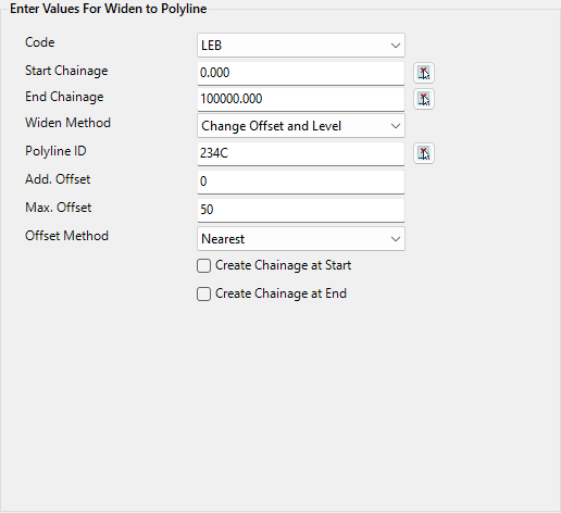
Set Code Offset to
Polyline |
This command can be used to set a Code to adopt
the offset of a polyline, with an optional additional offset, and maintain either the slopes or the level difference of the Section.
|
| Code |
Select the Code to adjust |
| Start Chainage: |
Select the Start Chainage from which the entry should apply. Type or use the pick list to select from the drawing. |
| End Chainage: |
Select the End Chainage at which the entry should stop applying. Type or use the pick list to select from the drawing. |
| Widen Method |
When the Code offset is adjusted to match the alignment, options for establishing the elevation of the code is optionally controlled by:
- Change Offset and Level: as the Code offset changes, the elevation of the Code is adjusted to maintain the current Section slope
- Change Offset - Keep Level: as the Code offset changes, the elevation of the Code is not adjusted (the relative height difference across the Section is maintained).
|
|
Polyline ID |
Click on the picker icon, then at the command prompt select the polyline in the
drawing.
The polyline ID (object handle) will display when the polyline is selected. |
|
Add. Offset |
Type in a value to add an additional offset to the offset position calculated
from the polyline. +ve values offset to the right and -ve offset to the
left of the selected polyline. |
|
Max. Offset |
Type in a maximum offset distance to search left/right of the alignment to
locate the polyline. Polyline geometry, up to the maximum offset value
specified, will be used to edit the code posiition.
A value of zero assumes no maximum offset is applied (polyline geometry is
always used) |
|
Offset Method |
Applies in the situation where the polyline can be intersected more than once
for a section.
- Nearest: use the nearest intersect with the polyline
- Furthest: use the furthest intersect with the polyline
Note: if no Offset Method is selected, then Furthest will be applied. |
| Create Chainage at START |
Store the Start Chainage in this form to be added as a Sampled Section on the current CSD object (see above for more details) |
| Create Chainage at END |
Store the End Chainage in this form to be added as a Sampled Section on the current CSD object (see above for more details) |
|
|
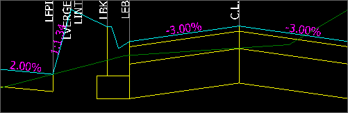
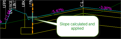
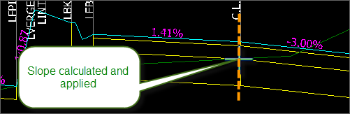
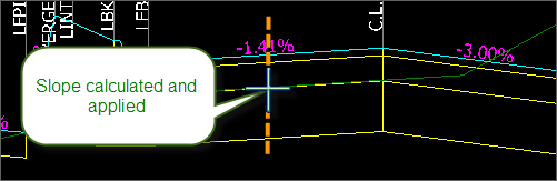
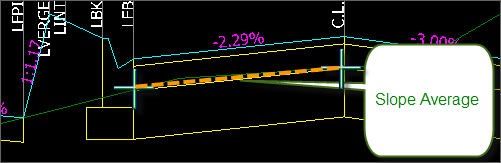
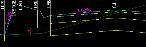
Match Section Slope to
Surface |
This command will set the Section crossfalls to match the Sampled Surface slope, with the user defining where the slope is calculated on the Sampled Surface in the Section.
Special Notes: An alignment is required for this command to control the Code offset. This variation may not interact well with other Variations applied to this Code.
|
| Code |
Select the Code to set a grade adjustment for |
| Start Chainage: |
Select the Start Chainage from which the entry should apply. Type or use the pick list to select from the drawing. |
| End Chainage: |
Select the End Chainage at which the entry should stop applying. Type or use the pick list to select from the drawing. |
| Alignment |
Select an alignment to control the offset location of the selected Code |
| Slope Calculated from Surface |
A slope is calculated from the selected surface and applied to the Code. The slope can be calculated by:
- At End of Section: at the outside edge of the Section matching the new Code offset, the slope is calculated at the surface and this slope is applied to the Section
- At Start of Section: at the inside edge of the Section matching the new Code offset, the slope is calculated at the surface and this slope is applied to the Section
- Between Section Start/End: the elevation is calculated at the start and end of the section and the average slope calculated is applied
- Between CL and Section End: the elevation is calculated at the CL Code and the end of the Section and the average slope calculated is applied
- Midway Between Section Start/End: the middle of the section is found, the slope of the surface is calculated at this location and is applied.
|
| Surface |
Select the surface from which to calculate slopes |
Example:
|
|
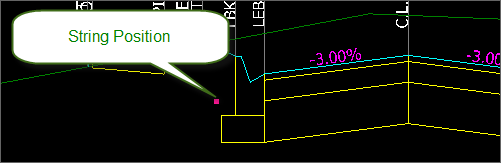
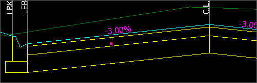
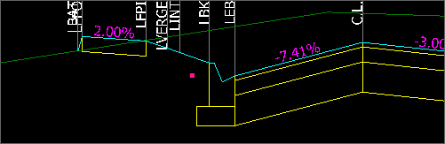
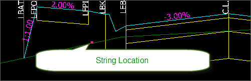
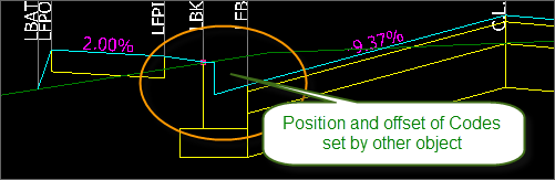
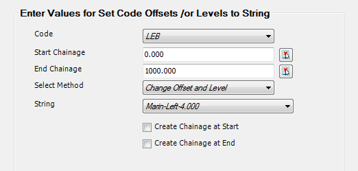
Set Code Offsets &/or Levels to String |
This command can be used to set a Code to adopt elevations and/or offsets of another CSD Object (normally a general String) designed. The Create/Edit Profile/String command can be used to create a String. This is a key requirement when it is required to independently grade elements of the cross section.
|
| Code |
Select the Code to adjust |
| Start Chainage: |
Select the Start Chainage from which the entry should apply. Type or use the pick list to select from the drawing. |
| End Chainage: |
Select the End Chainage at which the entry should stop applying. Type or use the pick list to select from the drawing. |
| Select Method |
Users can select how the String is used to control the selected Code:
- Hold Offset and level: do NOT change the offset or level of the Code to match the String (does nothing)
- Change Offset and Level: change BOTH the offset and the level of the Code to adopt the offset and level of the String
- Hold Level - Change Offset: do not change the level of the Code, but set the Code offset to match the String
- Hold Slope - Change Offset: Set the Code to adopt the elevation of the String, with the offset being calculated from the current slope of the Section. The slope is maintained and offset is adjusted to match the level of the String
- Hold Offset - Change Level: do not change the offset of the Code, but set the Code elevation to match the String
|
| String |
Select the String to use |
| Create Chainage at START |
Store the Start Chainage in this form to be added as a Sampled Section on the current CSD object (see above for more details) |
| Create Chainage at END |
Store the End Chainage in this form to be added as a Sampled Section on the current CSD object (see above for more details) |
Example:
|
|
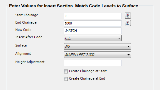
Insert Section & Match Code Levels to Surface |
This command can be used to create a new Code and Section and to have the Code adopt elevations relative to a surface, including applying an alignment offset.
Special Note: This Variation shouldn't be used in conjunction with other Variations on this Code - unexpected results will occur.
|
| Start Chainage: |
Select the Start Chainage from which the entry should apply. Type or use the pick list to select from the drawing. |
| End Chainage: |
Select the End Chainage at which the entry should stop applying. Type or use the pick list to select from the drawing. |
| New Code |
Type a name for the new Code |
| Insert After Code |
Select an existing Code on the cross section to insert this Code after. Sections outside of the existing Code will be moved and reconnected to the New Code |
| Surface |
Pick the surface to match elevations to |
| Alignment |
The Code must be set to use an alignment for offset location |
| Height Adjustment |
Optionally type an elevation to be above (+) or below (-) the selected Surface |
| Create Chainage at START |
Store the Start Chainage in this form to be added as a Sampled Section on the current CSD object (see above for more details) |
| Create Chainage at END |
Store the End Chainage in this form to be added as a Sampled Section on the current CSD object (see above for more details) |
Example:
| Before |
After |
 |
 |
|
|
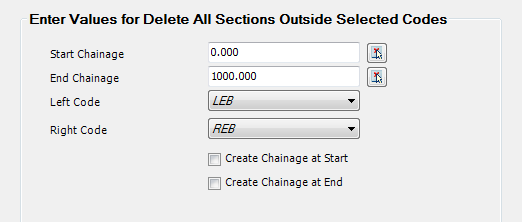
Delete All Sections Outside Selected Codes |
This command provides an efficient method for remove all Codes and Sections outside of a selected left and right side Code, not including the batter codes.
|
| Start Chainage: |
Select the Start Chainage from which the entry should apply. Type or use the pick list to select from the drawing. |
| End Chainage: |
Select the End Chainage at which the entry should stop applying. Type or use the pick list to select from the drawing. |
| Left Code |
Set the left Code to keep (all Codes outside of this will be deleted) |
| Right Code |
Set the right Code to keep (all Codes outside of this will be deleted) |
| Create Chainage at START |
Store the Start Chainage in this form to be added as a Sampled Section on the current CSD object (see above for more details) |
| Create Chainage at END |
Store the End Chainage in this form to be added as a Sampled Section on the current CSD object (see above for more details) |
|
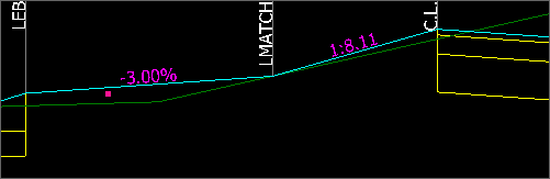
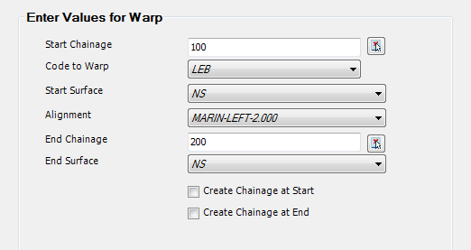
| Warp |
This command can be used to apply a linear change in crossfall for a Code, with the start and end crossfall being calculated from a surface.
|
|
Start Chainage: |
Select the Start Chainage from which the entry should apply. Type or use the pick list to select from the drawing. |
| Code to Warp: |
Select the required Code. |
| Start Surface: |
Select the surface at the starting chainage. This will set the crossfall of the Code at the Start Chainage |
| Alignment: |
Select the alignment that specifies the required offset for the Code. |
| End Chainage: |
Select the End Chainage at which the entry should stop applying. Type or use the pick list to select from the drawing. |
| End Surface: |
Select the surface at the end chainage. This will set the crossfall of the Code at the End Chainage. The software will linearly transition crossfalls between the Start Chainage and End Chainage. |
| Create Chainage at START |
Store the Start Chainage in this form to be added as a Sampled Section on the current CSD object (see above for more details) |
| Create Chainage at END |
Store the End Chainage in this form to be added as a Sampled Section on the current CSD object (see above for more details) |
|
|
|
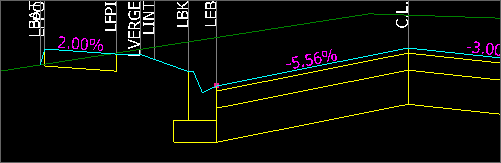
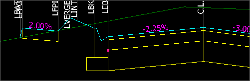
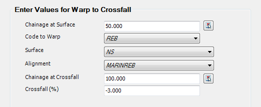
| Warp
to Crossfall |
Sets a Code to adopt the slope of an existing surface at a Start Chainage location and transition to a set crossfall an End Chainage. The Crossfall calculated is the average crossfall measured between the start and end of the Section.
|
| Chainage at Surface |
Start chainage where it is required to adopt the crossfall from the existing surface |
| Code to Warp |
Code to adjust |
| Surface |
Surface to adopt crossfalls from |
| Alignment |
Set the alignment to control the offset of the Code |
| Chainage at Crossfall |
Set the end chainage at which to apply a set Crossfall |
| Crossfall |
Set the Crossfall to apply at the End Chainage |
|
|
|
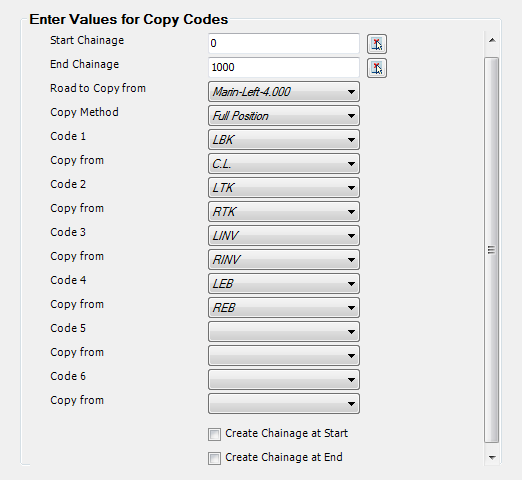
| Copy
Codes |
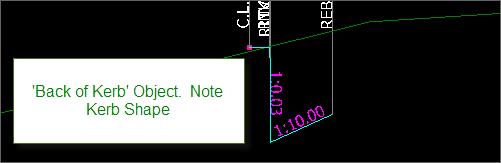
Copy Codes allows a user to pick Codes on the current CSD Object and have those Codes adopt the levels (and optionally offset) location of Codes from a DIFFERENT CSD Object. This is particularly useful when design from the 'outside in' - an example of this would be designing with a String on the Back of Kerb, but wanting the kerb codes to the face/lip of kerb to move relative to the Back of Kerb code. In this case, you would make a String for the kerb and apply a kerb template, then 'map' the String kerb shape onto equivalent codes on the centreline cross section.
Up to 6 Codes can be matched up in a single Copy Codes entry.
|
| Start Chainage: |
Select the Start Chainage from which the entry should apply. Type or use the pick list to select from the drawing. |
| End Chainage: |
Select the End Chainage at which the entry should stop applying. Type or use the pick list to select from the drawing. |
| Road to Copy From |
Pick the other CSD Object from which it is required to copy the Code offsets/levels from. |
| Copy Method |
When copying the Code information from the 'Road to Copy From' object, choose whether to adopt the full position from the other CSD Object or just the levels |
| Code 1 |
Select the Code from the CURRENT cross sections that is to be matched to the Code of the other CSD Object |
| Copy From |
Select the Code from the 'Road to Copy From' object that Code 1 is to match to |
| Code 2-6 |
Sect Codes from the CURRENT cross sections to match to another object Code |
| Copy From |
For each respective Code, set the Code to match to |
| Create Chainage at START |
Store the Start Chainage in this form to be added as a Sampled Section on the current CSD object (see above for more details) |
| Create Chainage at END |
Store the End Chainage in this form to be added as a Sampled Section on the current CSD object (see above for more details) |
|
Example:
|
|
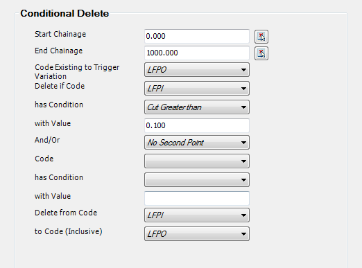
| Conditional Delete |
Conditional Deleting Codes provides an intelligent way for the software to determine that a collection of Codes need to be removed based on cut and/or fill conditions on a Code. The check is made at every sampled cross section.
Note: The Trigger Code must exist on the cross section for the Conditional Delete to apply, and it must be located outside of the Codes being deleted. It is strongly recommended to set the Trigger Code as the last code BEFORE the batter codes.
|
| Start Chainage: |
Select the Start Chainage from which the entry should apply. Type or use the pick list to select from the drawing. |
| End Chainage: |
Select the End Chainage at which the entry should stop applying. Type or use the pick list to select from the drawing. |
| Code Existing to Trigger Variation |
Pick a Trigger Code. Note: The Trigger Code must exist on the cross section for the Conditional Delete to apply, and it must be located outside of the Codes being deleted. It is strongly recommended to set the Trigger Code as the last code BEFORE the batter codes. |
| Delete if Code |
Code to check for cut/fill conditions. If the Code meets the cut/fill trigger conditions, then Codes are deleted |
| has Condition |
Set the first conditional check on the Code. Options are:
| Cut Greater Than |
If the Cut exceeds the with Value parameter below then the conditions for Code deletion are met |
| Cut Less Than |
If the Cut is less than the with Value parameter below then the conditions for Code deletion are met |
| Fill Greater Than |
If the Fill exceeds the with Value parameter below then the conditions for Code deletion are met |
| Fill Less Than |
If the Cut is less than the with Value parameter below then the conditions for Code deletion are met |
| Always |
Always apply the Code deletions |
|
| With Value |
Set the value to apply to the first condition (the preceding pick box) |
| And/Or |
Optionally set a second conditional check on the Code to determine if Codes should be deleted. Options are
| No Second Point |
Do not apply a secondary conditional check |
| And |
BOTH conditions must be met. Second Code and condition check become valid |
| Or |
Either condition is met. Second Code and condition check become valid |
|
| Code |
Select a second Code to check (this can be the same Code as for the previous conditional check |
| has Condition |
Set the second conditional check on the Code. Options are:
| Cut Greater Than |
If the Cut exceeds the with Value parameter below then the conditions for Code deletion are met |
| Cut Less Than |
If the Cut is less than the with Value parameter below then the conditions for Code deletion are met |
| Fill Greater Than |
If the Fill exceeds the with Value parameter below then the conditions for Code deletion are met |
| Fill Less Than |
If the Cut is less than the with Value parameter below then the conditions for Code deletion are met |
| Always |
Always apply the Code deletions |
|
| With Value |
Set the value to apply to the second condition (the preceding pick box) |
| Delete From Code |
Select the first Code to delete (pick the Code closest to the centreline |
| to Code (Inclusive) |
Select the second Code to delete. All Codes and Sections between these two Codes will be deleted. |
|
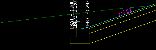
Example:
| Before |
After |
|

|
Where the Conditions aren't met
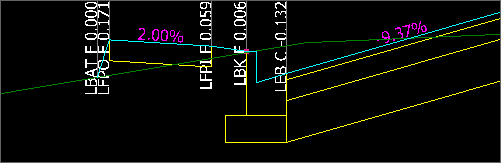
Where the Conditions are met:
|
|
|
| Comment |
This command gives the ability to add a
Comment entry to the list. This could be used as a separator to describe groups of variations
|
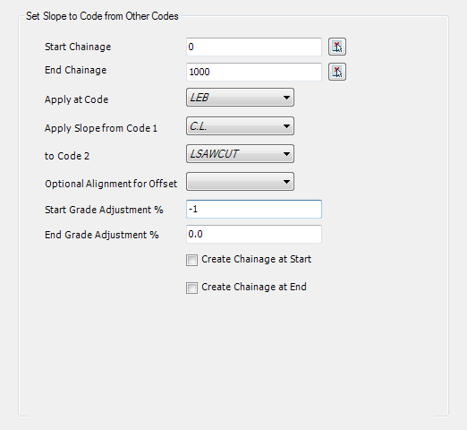
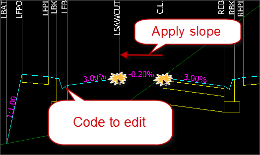
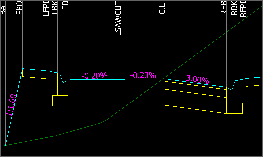
| Match
Section Slope to Codes |
Copy the slope from two design codes on the cross section and apply the calculated crossfall to a selected code. Codes used for slope calculation must be located on the same side as the code being edited, and be between the code being edited and the centreline.
|
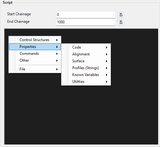
| Script |
Add a script to execute multiple cross section edits. This is written
in the Civil Site Design 'ScriptX' programming format.
For more details on writing
ScriptX files, review this documentation:
www.civilsurveysolutions.com.au/downloads/CSD/Documents/ScriptX-ProgrammersReference.pdf
|
| Start Chainage: |
Select the Start Chainage from which the entry should apply. Type or use the pick list to select from the drawing. |
| End Chainage: |
Select the End Chainage at which the entry should stop applying. Type or use the pick list to select from the drawing. |
|
Script Input Box |
Right click to add elements.
Type to create and edit the script.
Script format as described here:
www.civilsurveysolutions.com.au/downloads/CSD/Documents/ScriptX-ProgrammersReference.pdf
|
|
|
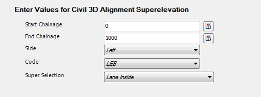
C3D Alignment Super |
The software is able to read the crossfall outputs from the Civil 3D Alignment Superelevation and apply these values to Codes on the cross sections. The Super rotation is applied from the start of the Section to the Code. Inputs are as follows:
|
| Start Chainage |
Select the Start Chainage from which the entry should apply. Type or use the pick list to select from the drawing. |
| End Chainage |
Select the End Chainage at which the entry should stop applying. Type or use the pick list to select from the drawing. |
| Side |
In the Civil 3D Superelvation table, users set the superelevation to apply to the Left and Right sides. Select the Side to apply here |
| Code |
Select the Code to adjust crossfall for |
| Super Selection |
Select which aspect of the superelevation from Civil 3D to apply:
- Inside Shoulder
- Outside Shoulder
- Inside Lane
- Outside Lane
|
|
|
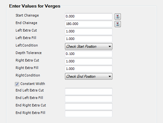
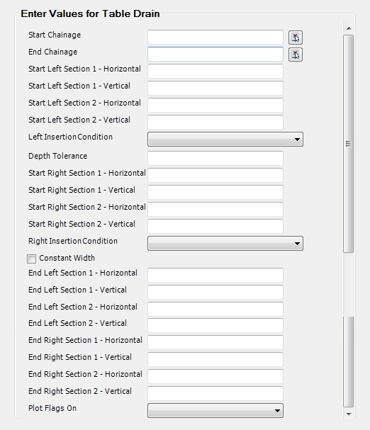
Table Drains |
This command allows a drain (ditch) to be added AFTER the template section has been computed (before the Batter). The Table Drain consists of two Sections of set width/height, one set for the start of the alteration the other for the end. This allows for the provision of a transition section of table drain if required. A conditional cut check able to be applied with the use of the insertion conditions pulldown.
|
| Start Chainage |
Select the Start Chainage from which the entry should apply. Type or use the pick list to select from the drawing. |
| End Chainage |
Select the End Chainage at which the entry should stop applying. Type or use the pick list to select from the drawing. |
| Start left Section 1 - Horizontal |
Left horizontal at Start Chainage - first leg |
| Start Left Section 1 - Vertical |
Left vertical - first leg (depth + is down) |
| Start left Section 2 - Horizontal |
Left horizontal - 2nd leg (leave blank if no 2nd leg) |
| Start Left Section 2 - Vertical |
Left vertical - 2nd leg (leave blank if no 2nd leg) |
| Left Insertion Condition |
Select from
- Always
- When Start of Table Drain is in Cut
- When end of Section 1 is in cut
- When end of Section 2 is in cut
This selection, in conjunction with the Depth Tolerance controls the application of the drain, depending on the amount of cut at the selected point.
|
| Depth Tolerance |
Used to provide a tolerance to the cut depth at the Left Condition point. The amount of cut must be GREATER than the tolerance for the drain to be applied. Use 0.000 if no tolerance check is required. |
| Set Right Section 1 - Horizontal |
Right horizontal - first leg |
| Set Right Section 1 - Vertical |
Right vertical - first leg (depth + is down) |
| Set Right Section 2 - Horizontal |
Right horizontal - 2nd leg (leave blank if no 2nd leg) |
| Set Right Section 2 - Vertical |
Right vertical - 2nd leg (leave blank if no 2nd leg) |
| Right Condition |
see left condition above for an explanation. |
| Constant Width |
Check this ON if the dimensions do not change between the start and the end chainages |
| End values... |
The values to be specified at the end chainage. In-between, the dimensions are interpolated, unless Constant Width is checked ON. |
| Plot Flags On |
Sets whether the codes will be plotted out on the cross sections. Yes = will plot, No = will not plot. |
|
|
Batters |
This series of commands allow the designer to set the Batters to behave differently over selected chainage ranges. This is an override to the Batters as defined in any Templates applied to the object.
Notes: Batters are sorted in REVERSE order in the batter listing, so when batter overrides overlap the batter condition specified first in the list will override other batter override entries. Batter entries will override each other - they are not able to be compounded together. Users are encouraged to make use of the Left and Right side controls to enforce what should occur
When a Batter override is to be added, a form will display listing the available batter overrides. Select a Batter from the list, then select the Insert Position. This can be set in the batter overrides list as follows:
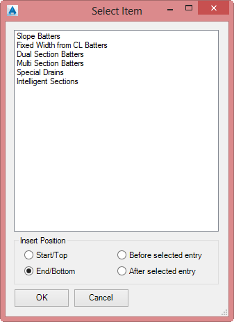
- Start/Top: top of list
- End/Bottom: end of list
- Before Selected Entry: above the entry you had highlighted at the time of clicking Add Entry
- After Select Entry: below the entry you had highlighted at the time of clicking Add Entry
Each Batter override is listed, below:
|
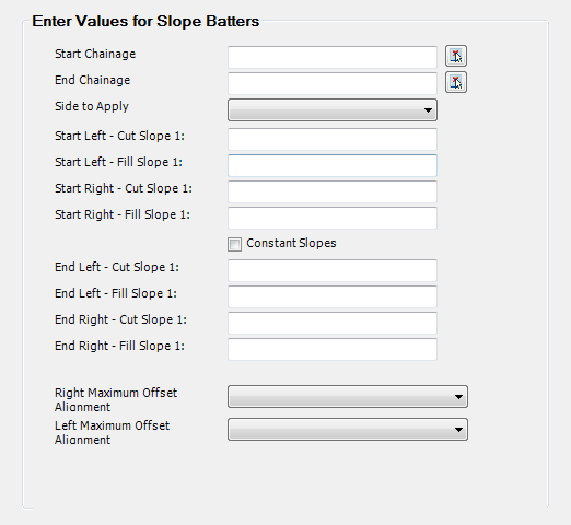
Slope Batters |
Adjust the Batters based on Slope. Blank entries will act to STOP Batters from being calculated.
Inputs are as follows:
| Start Chainage |
Select the Start Chainage from which the entry should apply. Type or use the pick list to select from the drawing. |
| End Chainage |
Select the End Chainage at which the entry should stop applying. Type or use the pick list to select from the drawing. |
| Side to Apply |
Select override batters to apply Left, Right or Both sides of the centreline |
| Start Left - Cut Slope 1: |
Cut slope override to apply Left side at the Start Chainage. Blank the field to omit batters. |
| Start Left - Fill Slope 1: |
Fill slope override to apply Left side at the Start Chainage. Blank the field to omit batters. |
| Start Right - Cut Slope 1: |
Cut slope override to apply Right side at the Start Chainage. Blank the field to omit batters. |
| Start Right - Fill Slope 1: |
Fill slope override to apply Right side at the Start Chainage. Blank the field to omit batters. |
| Constant Slopes |
Tick on to apply same slope conditions between the Start and End Chainage. If not ticked on, put values in the End fields unless the batter is to be omitted |
| End Left - Cut Slope 1: |
Cut slope override to apply Left side at the End Chainage. Blank the field to omit batters. |
| End Left - Fill Slope 1: |
Fill slope override to apply Left side at the End Chainage. Blank the field to omit batters. |
| End Right - Cut Slope 1: |
Cut slope override to apply Right side at the End Chainage. Blank the field to omit batters. |
| End Right - Fill Slope 1: |
Fill slope override to apply Right side at the End Chainage. Blank the field to omit batters. |
| Right Maximum Offset Alignment |
Optional. If an alignment is specified then batters that extend beyond the specified alignment are forced to match the surface at the alignment offset. Slopes will be steepened.
Note: if no Slope values are specified but an alignment is selected, batters will ALWAYS match to the alignment offset |
| Left Maximum Offset Alignment |
Optional. If an alignment is specified then batters that extend beyond the specified alignment are forced to match the surface at the alignment offset. Slopes will be steepened.
Note: if no Slope values are specified but an alignment is selected, batters will ALWAYS match to the alignment offset |
|
|
Fixed Width Batters |
Adjust the Batters to be fixed width. Where batter entries overlap, change the Batter order.
Inputs are as follows:
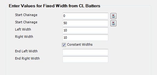
| Start Chainage |
Select the Start Chainage from which the entry should apply. Type or use the pick list to select from the drawing. |
| End Chainage |
Select the End Chainage at which the entry should stop applying. Type or use the pick list to select from the drawing. |
| Left Width |
Specify a Width (measured from the centreline) to extend batters to on the left |
| Right Width |
Specify a Width (measured from the centreline) to extend batters to on the right |
| Constant Widths |
Toggle this on to apply the same parameters between the Start and End Chainage. Linear interpolation will be applied where different widths are applied between start and end. |
| End Left Width |
Left width to apply at the End Chainage |
| End Right Width |
Right width to apply at the End Chainage |
|
|
Dual Section Batters |
Applies two batter conditions on both the left and right sides, with a guaranteed slope toward the centreline for the first batter section. For the first batter section, designers specify a minimum and maximum slope. The software will apply the minimum slope when the end of section would be in fill, up to the maximum slope when the section moves into cut. Once the maximum slope is met, a cut batter is applied to grade to the surface. In the case that the minimum slope is met and the end section is in fill, a fill slope section is applied to grade to the surface. 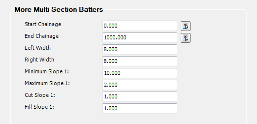
| Start Chainage |
Select the Start Chainage from which the entry should apply. Type or use the pick list to select from the drawing. |
| End Chainage |
Select the End Chainage at which the entry should stop applying. Type or use the pick list to select from the drawing. |
| Left Width |
Specify a Width (measured from the centreline) - the first batter section will be applied up to this width, with variable slopes between the Minimum Slope and Maximum Slope, depending on whether the end of the section is in cut or fill |
| Right Width |
Specify a Width (measured from the centreline) - the first batter section will be applied up to this width, with variable slopes between the Minimum Slope and Maximum Slope, depending on whether the end of the section is in cut or fill |
| Minimum Slope 1: |
Specify the minimum slope of the first batter Section. |
| Maximum Slope 1: |
Specify the maximum slope of the first batter Section. |
| Cut Slope 1: |
2nd batter slope to apply if the end of the first section is in cut. |
| Fill Slope 1: |
2nd batter slope to apply if the end of the first section is in fill |
|
|
Multi Section Batters (LEGACY) |
Multi Section Batter templates is a LEGACY command,
superseded by Intelligent Sections.
Inputs are as follows:
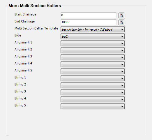
| Start Chainage |
Select the Start Chainage from which the entry should apply. Type or use the pick list to select from the drawing. |
| End Chainage |
Select the End Chainage at which the entry should stop applying. Type or use the pick list to select from the drawing. |
| Multi Section Batter Template |
Select a template to apply. Templates are created via the  Create/Edit Multi Section Batters command Create/Edit Multi Section Batters command |
| Side |
Pick the side to apply the Template to: left, right or both. |
| Alignment 1 - 5 |
Some of the batter conditions in the Multi Section Batter Template allow for alignment controls to be applied to manage the offsets |
| String 1 - 5 |
Some of the batter conditions in the Multi Section Batter Template allow for string controls to be applied |
|
|
Special Drains |
This batter method forms part of the CSD Express tools and will not be documented here.
Inputs are as follows:
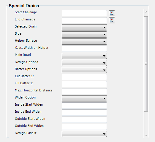
| Start Chainage |
Select the Start Chainage from which the entry should apply. Type or use the pick list to select from the drawing. |
| End Chainage |
Select the End Chainage at which the entry should stop applying. Type or use the pick list to select from the drawing. |
| Multi Section Batter Template |
Select a template to apply. Templates are created via the Create/Edit Multi Section Batters command |
| Side |
Pick the side to apply the Template to: left, right or both. |
| Alignment 1 - 5 |
Some of the batter conditions in the Multi Section Batter Template allow for alignment controls to be applied to manage the offsets |
| String 1 - 5 |
Some of the batter conditions in the Multi Section Batter Template allow for string controls to be applied |
|
|
Intelligent Sections |
Intelligent Sections Intelligent Section templates are created using the  Create/Edit Intelligent Sections command, and are applied to the cross sections using this Batter Override. Create/Edit Intelligent Sections command, and are applied to the cross sections using this Batter Override.
Inputs are as follows:
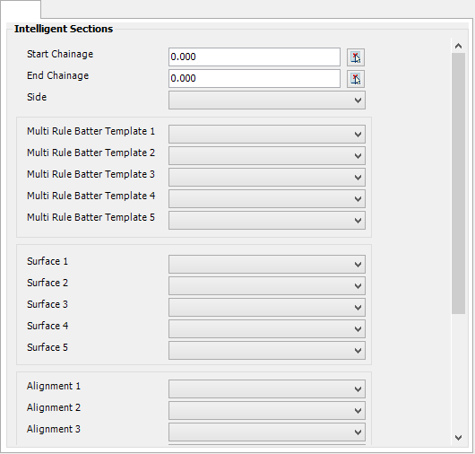
| Start Chainage |
Select the Start Chainage from which the entry should apply. Type or use the pick list to select from the drawing. |
| End Chainage |
Select the End Chainage at which the entry should stop applying. Type or use the pick list to select from the drawing. |
| Side |
Pick the side to apply the Template to: left, right or both. |
| Multi Rule Batter Template 1 - 5 |
Select a template to apply. Templates are created via the Create/Edit Intelligent Sections command.
If multiple Templates are assigned, Template 1 will be used first. After Template 1 has been applied, Template 2 will be applied, and so on to Template 5. |
| Surface 1 - 5 |
Intelligent Sections allow for sections of the template to extend to different surfaces - these as established as Surface 1 to Surface 5 in the Intelligent Sections template. If an alternate surface has been assigned to a segment of the Intelligent Sections template, use the pick list to assign the particular surface to project to for this string. |
| Alignment 1 - 5 |
Currently not used |
| String 1 - 5 |
Intelligent Sections allow for sections of the template to make use of Strings - these are established as Profile (String) 1 to Profile 5. If a string has been assigned to a segment of the Intelligent Sections template, use the pick list to assign the particular string to be used for the current string. |
|
|
|
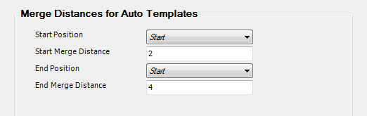
Auto Merge
The Auto Merge command is used ONLY with kerb returns and culdesacs when the Auto Template is in use.
By default, the elements of the template at the start and the end are merged uniformly (by linear interpolation) when the Auto Template is in use.
Using this interpolation means that the designer has to create a number of variations if there is a layback kerb at one and and an upright kerb at the other. In practice, this transition will occur towards one end and it will occur over a fairly short distance. The Auto Merge command makes this transition easy by
- enabling the starting template to be maintained for a specified distance
- maintaining the ending template for a specified distance
- merging from layback to upright in between these points
|
| Start Position |
Select Start or End |
| Start merge distance |
Enter the Distance from the start position for the template to be maintained without interpolation |
| End position |
Select Start or End. Generally the same as the start position (to avoid having to use the kerb length) |
| End merge distance |
Enter the Distance from the end position for the template to be maintained without interpolation |
Design Constraints
Design constraints are used as an aid to design, particularly when there are level constraints to be met. Design Constraints compute and display the maximum and minimum levels at a chainage (or along a Road length) that will meet overall limits in grade changes (crossfalls) from another CSD Object or constraint.
When the design constraints are used correctly, the maximum and minimum levels indicate the region where the design should pass. The design constraints are shown in the Vertical Grading Editor on both the long section and cross section display. If the design is between the maximum and minimum levels, then the crossfall from the constraint position has been met. If the level is outside the upper and lower limits, then the cross fall from the constraint has not been met.
Design constraints are used extensively to highlight level constraints in road reconstruction jobs where there is a need to match in to existing features (such as footpath, existing centreline levels, etc). Design constraints can be made from nearby CSD Objects or for other features(such as building lines, underground services, other road levels).
When a Design Constraint is to be added, a form will display listing the constraints. Select a constraint from the list, then select the Insert Position. This can be set in the constraints list as follows:
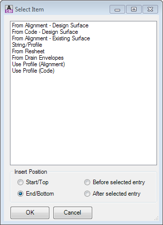
- Start/Top: top of list
- End/Bottom: end of list
- Before Selected Entry: above the entry you had highlighted at the time of clicking Add Entry
- After Select Entry: below the entry you had highlighted at the time of clicking Add Entry
Each Design Constraint is listed, below:
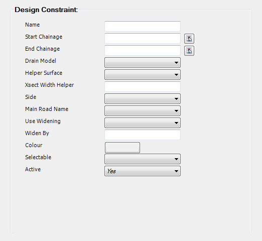
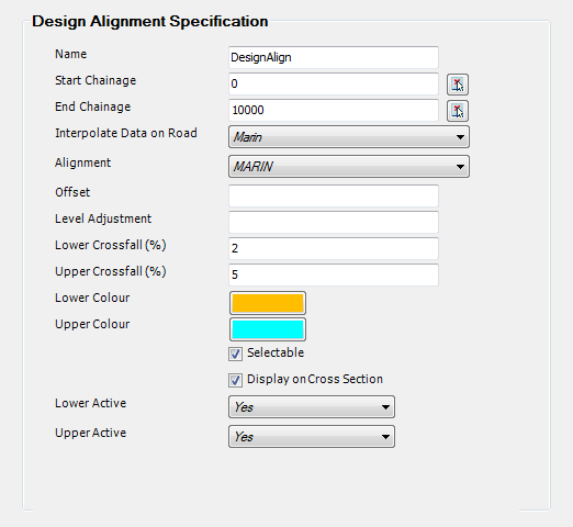
From Alignment - Design Surface
Displays design constraints on the current cross sections and Vertical Grading Editor window, with the reference point location determined by selecting an alignment (for offset location) and a CSD Object (for design levels)
Inputs are as follows:
|
| Name |
Name the constraint |
| Start chainage |
Select the Start Chainage from which the entry should apply. Type or use the pick list to select from the drawing. |
| End chainage |
Select the End Chainage at which the entry should stop applying. Type or use the pick list to select from the drawing. |
| Interpolate data on road |
Select road name to work with - generally the current road |
| Alignment |
Select the alignment to use for the Reference Point Offset (horizontal position) |
| Offset |
Optional offset increment from the alignment. The reference point will be defined at the offset location |
| Level adjustment |
Option level adjustment on the Reference Point elevation. |
| Lower XFall% |
Specify the lower crossfall |
| Upper XFall% |
Specify the upper crossfall |
| Lower colour |
Select a colour |
| Upper colour |
Select a colour |
| Selectable |
Check ON if it is required to be able to use these levels in the Vertical Grading to snap to. |
| Display on section |
Check ON if it is required to show the constraint on the cross section viewer |
| Lower/Upper Active |
Select Yes to make the lines Active |
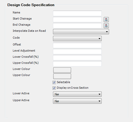
From Code - Design Surface Displays design constraints on the current cross sections and Vertical Grading Editor window, with the reference point location determined by selecting a Design Code (for offset location) and an CSD Object (for design levels)
Inputs are as follows:
|
| Name |
Name the constraint |
| Start chainage |
Select the Start Chainage from which the entry should apply. Type or use the pick list to select from the drawing. |
| End chainage |
Select the End Chainage at which the entry should stop applying. Type or use the pick list to select from the drawing. |
| Interpolate data on road |
Select CSD Object to work with - generally the current road |
| Code |
Select the Code from the CSD Object selected. |
| Offset |
Optional offset increment from the alignment. The reference point will be defined at the offset location |
| Level adjustment |
Option level adjustment on the Reference Point elevation. |
| Lower Crossfall% |
Specify the lower crossfall |
| Upper Crossfall% |
Specify the upper crossfall |
| Lower colour |
Select a colour |
| Upper colour |
Select a colour |
| Selectable |
Check ON if it is required to be able to use these levels in the Vertical Grading to snap to. |
| Display on section |
Check ON if it is required to show the constraint on the cross section viewer |
| Lower/Upper Active |
Select Yes to make the lines Active |
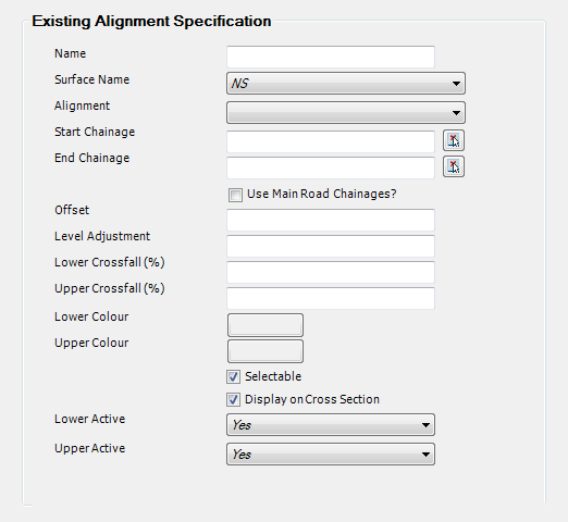
From Alignment - Existing Surface Displays design constraints on the current cross sections and Vertical Grading Editor window, with the reference point location determined by selecting an alignment (for offset location) a surface (for levels)
Inputs are as follows:
|
| Name |
Name the constraint |
| Surface Name |
Select a surface for the Reference Point level |
| Alignment |
Select an alignment for the Reference Point offset |
| Start chainage |
Select the Start Chainage from which the entry should apply. Type or use the pick list to select from the drawing. |
| End chainage |
Select the End Chainage at which the entry should stop applying. Type or use the pick list to select from the drawing. |
| Use Main Road Chainages? |
Check this to just use the chainages from the current road |
| Offset |
Optional adjustment to the horizontal location of the Reference Point |
| Level adjustment |
Option level adjustment on the Reference Point elevation. |
| Lower Crossfall% |
Specify the lower crossfall |
| Upper Crossfall% |
Specify the upper crossfall |
| Lower colour |
Select a colour |
| Upper colour |
Select a colour |
| Selectable |
Check ON if it is required to be able to use these levels in the Vertical Grading to snap to. |
| Display on section |
Check ON if it is required to show the constraint on the cross section viewer |
| Lower/Upper Active |
Select Yes to make the lines Active |
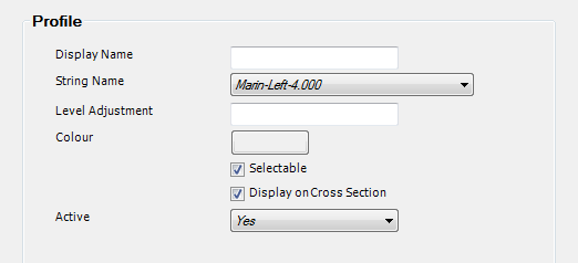
String/Profile Displays the levels of another CSD Object (Road, Kerb or other String)
Inputs are as follows:
|
| Display Name |
Name the constraint |
| String Name |
Select a String to show |
| Level Adjustment |
Set a height adjustment to apply to the String when displayed |
| Colour |
Select a colour |
| Selectable |
Check ON if it is required to be able to use these levels in the Vertical Grading to snap to. |
| Display on section |
Check ON if it is required to show the constraint on the cross section viewer |
| Active |
Select Yes to make the lines Active |
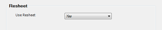
From Resheet This command will display the Resheet outputs.
Inputs are as follows:
|
| Use Resheet |
Select Yes or No |
From Drain Envelopes This command displays open Drain Envelopes created from an CSD Express tool. Details will not be documented.
Inputs are as follows:
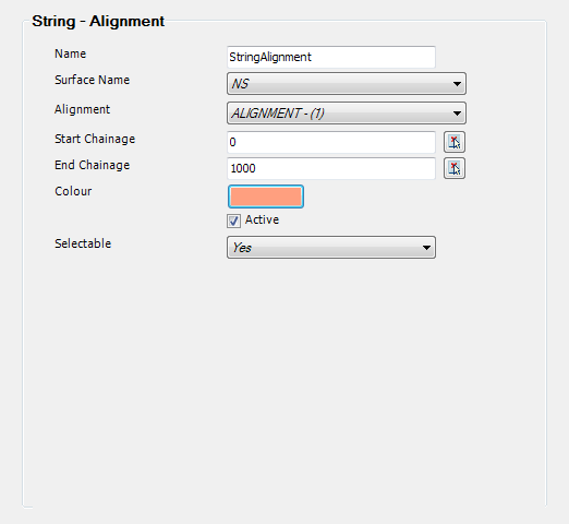
Use Profile - Alignment Displays surface levels at a selected alignment. The line is displayed in the Vertical Grading Editor window.
|
| Name |
Name the constraint |
| Surface Name |
Select a surface for levels |
| Alignment |
Select the string alignment |
| Start chainage |
Select the Start Chainage from which the entry should apply. Type or use the pick list to select from the drawing. |
| End chainage |
Select the End Chainage at which the entry should stop applying. Type or use the pick list to select from the drawing. |
| Colour |
Select a colour |
| Active |
Select Yes to make line Active |
| Selectable |
Check ON if it is required to be able to use these levels in the Vertical Grading to snap to. |
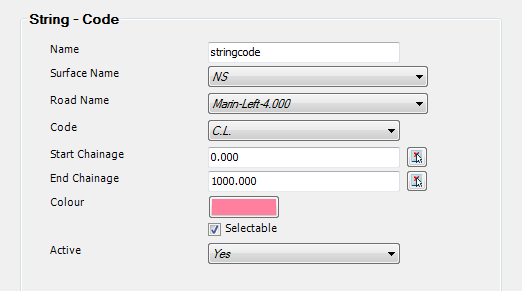
Use Profile - Code Displays surface levels for a Code on a selected CSD Object. The line is displayed in the Vertical Grading Editor window.
|
| Name |
Name the constraint |
| Surface Name |
Select a surface for levels |
| Road Name |
Select the CSD Object for offset location |
| Code |
Select Code for offset location |
| Start chainage |
Select the Start Chainage from which the entry should apply. Type or use the pick list to select from the drawing. |
| End chainage |
Select the End Chainage at which the entry should stop applying. Type or use the pick list to select from the drawing. |
| Colour |
Select a colour |
| Selectable |
Check ON if it is required to be able to use these levels in the Vertical Grading to snap to. |
| Active |
Select Yes to make line Active |
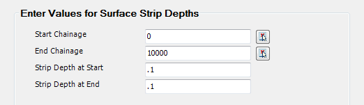
Stripping Stripping data is used to specify the depth of topsoil to be removed when calculating volumes. The stripping volume is calculated by applying a depth of material removal between the left and right extents of the design cross sections (normally batter to batter).
Note: if you specify overlapping chainage ranges, the FIRST range found is used. If there are any gaps in the data specification, then the strip depths are set to 0.0
Inputs are as follows:
|
| Start Chainage |
Select the Start Chainage from which the entry should apply. Type or use the pick list to select from the drawing. |
| End Chainage |
Select the End Chainage at which the entry should stop applying. Type or use the pick list to select from the drawing. |
| Strip Depth at Start |
Enter the strip depth at the start chainage |
| Strip Depth at End |
Enter the strip depth at the end chainage |
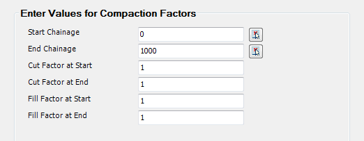
Compaction Factors
The Volume factors are used to scale the computed volumes. The factors used will vary depending on the material involved and the compaction required.
Inputs are as follows:
|
| Start Chainage |
Select the Start Chainage from which the entry should apply. Type or use the pick list to select from the drawing. |
| End Chainage |
Select the End Chainage at which the entry should stop applying. Type or use the pick list to select from the drawing. |
| Cut factor at start |
Enter the factor at the start chainage. Default value is 1.0 |
| Cut factor at end |
Enter the factor at the end chainage. Default value is 1.0 |
| Fill factor at start |
Enter the factor at the start chainage. Default value is 1.0 |
| Fill factor at end |
Enter the factor at the end chainage. Default value is 1.0 |
Subgrade Definition This area allows users to override previously applied subgrade controls. There are also a range of legacy subgrade templates that can be applied.
When a Subgrade is to be added, a form will display listing the constraints. Select from the list, then select the Insert Position. This can be set in the list as follows:
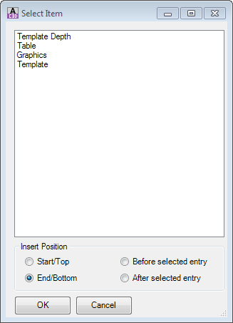
- Start/Top: top of list
- End/Bottom: end of list
- Before Selected Entry: above the entry you had highlighted at the time of clicking Add Entry
- After Select Entry: below the entry you had highlighted at the time of clicking Add Entry
Each entry is listed, below:
Template Depth
This is a legacy option to open older subgrades that only showed a datum.
Inputs are as follows:
|
| Start chainage |
Select the Start Chainage from which the entry should apply. Type or use the pick list to select from the drawing. |
| End chainage |
Select the End Chainage at which the entry should stop applying. Type or use the pick list to select from the drawing. |
| Template Name |
Select the Template |
| Depth |
Type in a depth |
| Left Link |
tick to show left links |
| Right link |
tick to show right link |
| Merge |
tick to merge multiples |
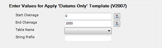
Table This is a legacy option to open older subgrades.
Inputs are as follows:
|
| Start chainage |
Select the Start Chainage from which the entry should apply. Type or use the pick list to select from the drawing. |
| End chainage |
Select the End Chainage at which the entry should stop applying. Type or use the pick list to select from the drawing. |
| Template Name |
Select the Template |
| String Prefix |
set a prefix |
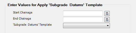
Graphics This is a legacy option to open older subgrades.
Inputs are as follows:
|
| Start chainage |
Select the Start Chainage from which the entry should apply. Type or use the pick list to select from the drawing. |
| End chainage |
Select the End Chainage at which the entry should stop applying. Type or use the pick list to select from the drawing. |
| Subgrade Datums Template |
Select the Template |
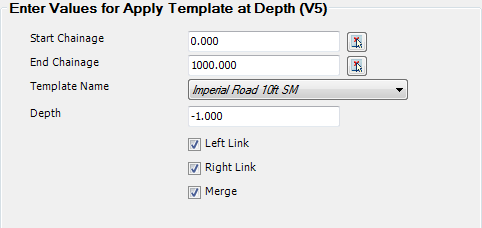
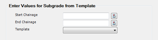
Template This is the current Template method for changing subgrade templates.
Inputs are as follows:
|
| Start chainage |
Select the Start Chainage from which the entry should apply. Type or use the pick list to select from the drawing. |
| End chainage |
Select the End Chainage at which the entry should stop applying. Type or use the pick list to select from the drawing. |
| Template |
Select the Template from the list of Local Templates in your project. |
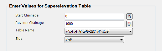
Template Super Many organisations (including the Road Traffic Authority of NSW) have developed superelevation tables, which define distances and changes to crossfalls and widths of multiple Codes of the cross section (and optionally offsets to the centreline to account for spirals leading into and out of the curves). These types of templates can be created via the  Create/Edit Super Table command and can be applied to the cross sections here.
It is required for the designer to ascertain where to start the superelevation table and when to apply it in reverse at the end of the curves.
Note: if you specify overlapping chainage ranges then the first Superelevation Table will overwrite the second - they will not merge or average offsets and slopes. For switchback curves or where reduce superelevation lengths are required, users are encouraged to create a superelevation table to suit.
Inputs are as follows:
|
| Start Chainage |
Select the Start Chainage from which the entry should apply. Type or use the pick list to select from the drawing. |
| End Chainage |
Select the End Chainage at which the entry should stop applying. Type or use the pick list to select from the drawing. |
| Table Name |
Pick the table to apply. Tables are created via the Create/Edit Super Table command |
| Side |
Specify the curve direction. |
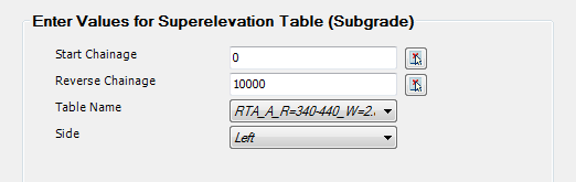
Subgrade Super This is a legacy command for applying subgrade Templates (which is no longer used) - this is in place for legacy data.
Inputs are as follows:
|
| Start Chainage |
Select the Start Chainage from which the entry should apply. Type or use the pick list to select from the drawing. |
| End Chainage |
Select the End Chainage at which the entry should stop applying. Type or use the pick list to select from the drawing. |
| Table Name |
Pick the table to apply. Tables are created via the Create/Edit Super Table command |
| Side |
Specify the curve direction. |
Legacy Verges This is a legacy command and is here to support legacy data only.
Inputs are as follows:
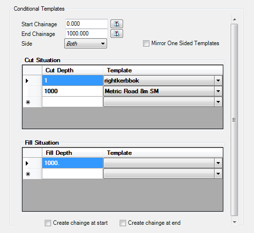
Conditional Templates Conditional Templates provide a means of specifying different Templates to automatically apply based on the cut or fill depth at the centreline. The software will establish the required template for each cross section based on the conditional list, and update the applied Template as the section is raised and lowered at the centreline. These act as an override to the Templates entries of the Design Data Form.
Note: Blank fields are treated as accepting the default Template assigned in the Templates entry of the Design Data Form.
|
| Start Chainage: |
Select the Start Chainage from which the entry should apply. Type or use the pick list to select from the drawing. |
| End Chainage: |
Select the End Chainage at which the entry should stop applying. Type or use the pick list to select from the drawing. |
| Side |
Pick the Side to apply the Templates to |
| Mirror One Sided Templates |
This will flip one sided templates to mirror on the opposite side of the centreline |
| Cut Situation |
Spreadsheet for specifying the different Templates to apply based on the depth of cut at the centreline |
| Cut Depth |
Specify different Cut Depths. For each value specified, the software will apply the selected Template in the same row UP TO THIS DEPTH OF CUT. |
| Template |
For a selected Cut Depth, specify the Template to apply. |
| Fill Situation |
Spreadsheet for specifying the different Templates to apply based on the depth of fill at the centreline |
| Fill Depth |
Specify different Fill Depths. For each value specified, the software will apply the selected Template in the same row UP TO THIS DEPTH OF FILL. |
| Template |
For a selected Fill Depth, specify the Template to apply. |
| Create Chainage at START |
Store the Start Chainage in this form to be added as a Sampled Section on the current CSD object (see above for more details) |
| Create Chainage at END |
Store the End Chainage in this form to be added as a Sampled Section on the current CSD object (see above for more details) |
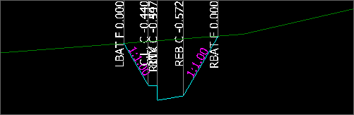
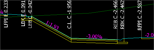
Example:
| Cut Depth Range set to 1m - Kerb Template Applied |
Cut Depth Range beyond 1m - Typical Road Template Applied |
 |
 |
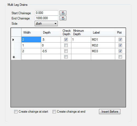
Multi Leg Drains Multi Leg Drains adds a sequence of codes at the end of the cross section (before any Batters) with the user specifying the collection of Codes (and Sections) to add.
A conditional depth check can be applied to any of the Codes specified in the table - the first Code where the depth condition is met will trigger all Codes in the table to be added.
|
| Start Chainage: |
Select the Start Chainage from which the entry should apply. Type or use the pick list to select from the drawing. |
| End Chainage: |
Select the End Chainage at which the entry should stop applying. Type or use the pick list to select from the drawing. |
| Side |
Pick the Side to apply the Multi Leg Drain to. Options are Left, Right or Both |
| Leg Table |
Table allowing for the specification of multiple Segments (Codes) to be added as well as a Depth check to determine if the table of Codes should be included. Use [Tab] at the last entry to add a new line |
| Width |
Specify the width of the Section |
| Depth |
Specify the Depth. + is measured downwards from the previous Code and - is measured upwards |
| Check Depth |
Tick to check the Code depth when it is inserted. If the Code is less than the specified depth, the table of Codes and Sections will not be added. If any of the Check Depths are valid, the full table of Codes and Sections will be added. Untick to add the table in all conditions |
| Minimum Depth |
If Check Depth is ticked on, this is the Depth that the Code must exceed in order to be added. Only positive values are accepted, with depth being measured positive for cut. |
| Label |
Set the Code name to apply to the end of the Section |
| Plot |
Tick ON to label this Code on the cross section plots. |
Example:
| Multi Leg Drain meeting the Depth Condition |
Multi Leg Drain not meeting the Depth Condition - not included. |
 |
 |
 Sync Start/End Cross Section Viewer