Create/Edit Cul-de-sac
| Icon: |
|
Introduction
The Create/Edit Cul-de-sac command is a powerful routine to automate the process of creating cul-de-sacs.
- Create New Cul-de-sac
- Use simple parametric inputs to generate/update an alignment for the cul-de-sac, including match in to the edge of the roadway to which it connects.
- Assign a cross section Template as part of the vertical design.
- Assign vertical controls to 'read in' the road levels and apply them to parts of the cul-de-sac.
- Generate a profile that is automatically and continuously matched to the shape and levels of the Road to which it connects.
- Edit Existing Cul-de-sac
- Adjust horizontal inputs to update the cul-de-sac alignment, whilst maintaining connectivity to the Road.
- Edit the crown extents and the extent of automatic profile matching to the connecting Road.
Once created the Cul-de-sac profile can be edited immediately via the  Vertical Grading Editor. Part of the cul-de-sac from the start and end of the alignment will obtain elevations from the connecting Road String cross sections.
Special Notes on Cul-de-sac Templates - Template Details
| Special Notes: | Users must first create the Road to which the cul-de-sac is connected. Use the |
| For Civil 3D
Users, alignments created can include an alignment description with the prefix cds- (not case sensitive).
For Non-Civil 3D Users, alignments should be be created as Type 'Cul-de-sac'. |
|
|
The direction of the cul-de-sac alignment is worked out as the OPPOSITE of the
|
|
| The data used to create the horizontal geometry is stored, so that it is easy to adjust the shape of the cul-de-sac.
For Civil 3D Users, using the command For Non-Civil 3D Users, the adjustment of the cul-de-sac will largely be automatic. The above command can be used if required. |
ALWAYS extend the Road beyond the end of the cul-de-sac - the software uses the road levels to automate the profile of the cul-de-sac, and will trim back the Road at the time of:
Details
This command can be used to Create as well as Edit a cul-de-sac. The form suppresses some functionality in the edit mode.
Creating/Editing a Cul-de-sac
Upon starting the command the command prompt reads:
Select Cul-de-sac to Edit [Enter if Creating a New Cul-de-sac Alignment]
Options are:
- Creating a NEW cul-de-sac: Press the [Enter] button on the keyboard
- Editing an existing cul-de-sac: click on or near to the alignment in the drawing
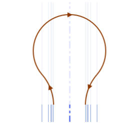
Once the alignment is selected or the [Enter] button is pressed, the following form is displayed. Hover over the different inputs to see the central diagram and supporting notation update:
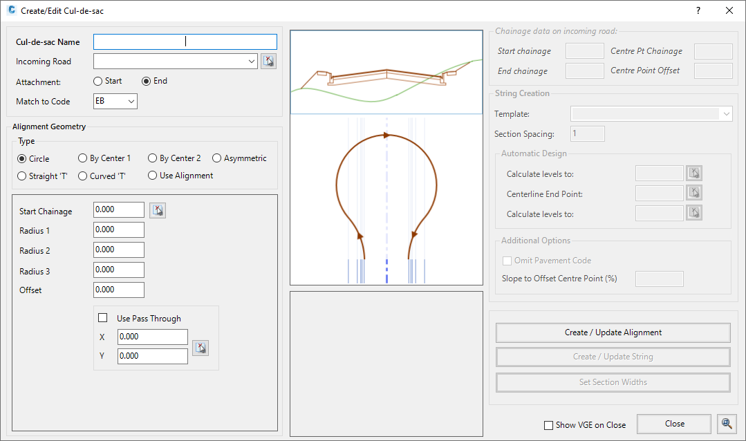 |
Main Processes
The main processes for creating/editing a cul-de-sac is as follows:
- Cul-de-sac definition and connectivity established
- Cul-de-sac horizontal geometry parameters set
- Create/Update cul-de-sac (Alignment) geometry
- Set profile controls for the cul-de-sac interaction with the incoming Road
Step 1: Cul-de-sac Definition
A number of options are provided at the top of the form for the user to define the cul-de-sac name and connectivity to the Road, as follows:
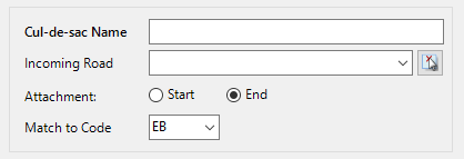
For a new cul-de-sac, users need to define: |
|
| Cul-de-sac Name | This is the name that will be assigned to the new Road element created in Civil Site Design, as well as the name of the alignment that will be created. |
| Incoming Road | Use the pick list to select a Road for the cul-de-sac to connect to. |
| Attachment | In order to get the alignment direction correct, the user must select whether the alignment is being created near the Start or the End of the alignment. This option is initially completed automatically based on the nearest end where the user clicked to select the the road aligment, but can be over-ridden with the Start or End button afterwards. |
| Match to Code | Civil Site Design automates the horizontal alignment creation of the cul-de-sacs by locating a particular code from the Road. This code normally defines the edge of the roadway, and sets where the cul-de-sac alignment should connect.
Use the pick list to select the appropriate Code from the incoming Road cross section. |
A sketch demonstrates the different aspects of these options:
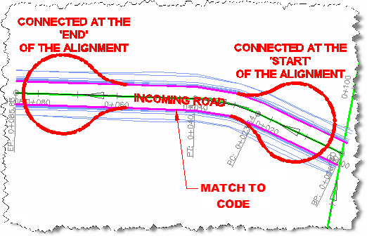 |
For an existing cul-de-sac that is being edited, the Cul-de-sac Name parameter is greyed out and unable to be edited.
Step 2: Setting the Horizontal Design Parameters
There are a number of different horizontal design options for the cul-de-sac. For each of these options (excepting the Specify Alignment), the user is able to type in radii and length values and specify/pick setout geometry points. The software will use this information directly to build an alignment and use this for creating the cul-de-sac.
Cul-de-sac configurations are shown below. Simply click on one of the buttons from the image below for further information on that design method:
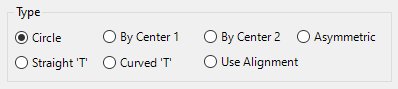
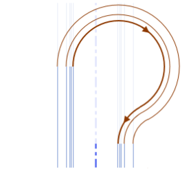
Circular Cul-de-sac
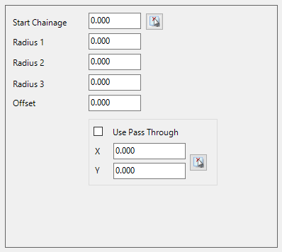
This method of creation requires the user to select a Start Chainage and three Radii (approach Radius, bowl radius and return Radius).
As an alternative to specifying the Start Chainage users could tick the box to specify a Pass Through point in the bowl of the cul-de-sac. If the pass through point is selected, the position of the cul-de-sac alignment is adjusted so that this point lies on the new cul-de-sac alignment. If it is impossible to have the cul-de-sac alignment pass through this point, then an error message is issued.
Double click in the Start Chainage cell or click on the ![]() icon to select a Starting Chainage off screen. Click on the
icon to select a Starting Chainage off screen. Click on the ![]() select icon to graphically locate the Pass Through point.
select icon to graphically locate the Pass Through point.
 |
 |
| Start Chainage | Specify the Starting Chainage by typing in the box, or click on the |
| Radius 1 | Enter the Approach Radius |
| Radius 2 | Enter the Bowl Radius |
| Radius 3 | Enter the Return Radius |
| Offset | Enter a value (positive or negative) to offset the centre of the cul-de-sac. Measured perpendicularly from the Main Road Centreline. Note: the maximum offset must be less than Radius 2 minus the road lane width (C.L. code to the Edge Code that the cul-de-sac connects to) |
| Use Pass Through | Tick the box to specify a Pass Through Point in the bowl of the cul-de-sac. Click on the Note: If the pass through point is selected, the position of the cul-de-sac alignment is adjusted so that this point lies on the new cul-de-sac alignment. If it is impossible to have the cul-de-sac alignment pass through this point, then an error message is issued. |
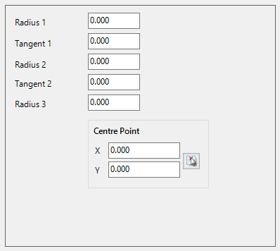
By Center (Version One) - Circular Cul-de-sac
As above, except that a Centre Point is specified for the court bowl, instead of a Start Chainage. The Centre Point is determined from the selection of an arc in the drawing.
 |
 |
| Radius 1 | Enter the Approach Radius |
| Radius 2 | Enter the Bowl Radius |
| Radius 3 | Enter the Return Radius |
| Tangent 1 | Type in a Tangent length. Leave at 0 to omit a tangent. |
| Tangent 2 | Type in a Tangent length. Leave at 0 to omit a tangent. |
| Centre Point | This is determined from the selection of a circle or arc in the drawing. The Centre Point will be located at the centre of the circle or arc.
Click the |
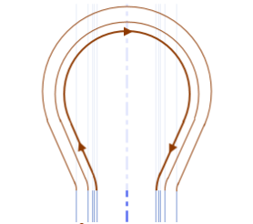
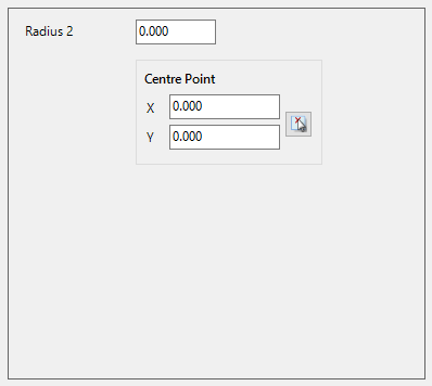
By Centre (Version2) - Asymmetric (Club Foot) Cul-de-sac
As above, except that setout of the bowl is made by selecting the centre point of the bowl. The Centre Point is determined from the selection of an arc in the drawing.
 |
 |
| Radius 2 | Enter the Approach Radius |
| Centre Point | This is determined from the selection of a circle or arc in the drawing. The Centre Point will be located at the centre of the circle or arc.
Click the |
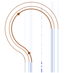
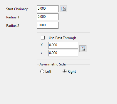
Asymmetric (Club Foot) Cul-de-sac
The cul-de-sac bowl is offset so that it bulges out one side only. An additional pick box will display for the user to select LEFT or RIGHT side for the bulge.
Select the Starting chainage, approach radius and bowl radius.
 |
 |
||||
| Start Chainage | Specify the Starting Chainage by typing in the box, or click on the |
||||
| Radius 1 | Enter the Approach Radius. | ||||
| Radius 2 | Enter the Bowl Radius. | ||||
| Use Pass Through | Tick the box to specify a Pass Through Point in the bowl of the cul-de-sac. Click on the Note: If the pass through point is selected, the position of the cul-de-sac alignment is adjusted so that this point lies on the new cul-de-sac alignment. If it is impossible to have the cul-de-sac alignment pass through this point, then an error message is issued. |
||||
| Asymmetric Side |
|
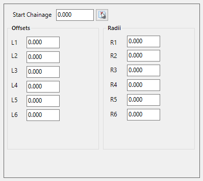
Straight T Cul-de-sac
As described below. Ensure that reasonable figures are set here otherwise a message will display advising that there is no geometric solution.
 |
 |
| Start Chainage | Specify the Starting Chainage by typing in the box, or click on the |
| Offsets | Enter offset distances measured from the points specified in the above diagram. As you hover over the different entries, the supporting image will update to show you which length dimension (L) you are editing. Values must be greater than 0.01m. |
| Radii | Enter the radii of curves as specified in the above diagram. As you hover over the different entries, the supporting image will update to show you which radius dimension (R) you are editing. Values must be greater than 0.01m. |
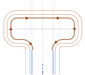
Curved T Cul-de-sac
As described below. Ensure that reasonable figures are set here otherwise a message will display advising that there is no geometric solution.
 |
 |
| Start Chainage | Specify the Starting Chainage by typing in the box, or click on the |
| End Chainage | Specify the End Chainage by typing in the box, or click on the |
| Offsets | Enter offset distances measured from the points specified in the above diagram. Values must be greater than 0.01m. |
| Radii | Enter the radii of curves as specified in the above diagram. Values must be greater than 0.01m and less than the adjacent Offset length. For example, R2 must be less than L2. |
| Angles | Enter the angles (in degrees) measured from the Main Road Alignment. Angle #1 for the left leg and angle #2 for the right leg. |
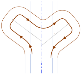
Use Alignment
Designers are able to create their own alignment for the cul-de-sac. In order for this to be successful the Designer must:
- Correctly match the start/end of the cul-de-sac alignment up to the selected connection label/point code for the Road String.
- Set the alignment direction to be the direction of vehicular movement around
the cul-de-sac (for driving on the left side of road, this is a Counter
Clockwise movement. For driving on the right side of the road, this is a
Clockwise movement). This would be the OPPOSITE direction as set out in
 Active Drawing Settings form
(Design Settings tab > Base ARD Settings Frame > Kerb Direction).
Active Drawing Settings form
(Design Settings tab > Base ARD Settings Frame > Kerb Direction). - For Non-Civil 3D Users, set the alignment Type to 'Cul-De-Sac'
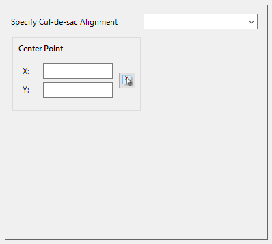
Use the pick list to select the required alignment in the drawing to use for the cul-de-sac horizontal geometry. All Alignments will be listed in the pick list. Cul-De-Sac Alignments already created or defined as a 'Cul-De-Sac' (in CAD versions, users set the alignment Type, and in Civil 3D users can type cds- in the Alignment Description field) will appear at the top of list and will be separated from all other alignments available by a couple of blank lines.
 |
|
| Specify Cul-de-sac Alignment | Select the cul-de-sac alignment from the list. |
| Centre Point X | Specify the X value for the centrepoint of the bowl radius of the cul-de-sac (or approximate in the case of a non-circular cul-de-sec) by typing in the box, or click on the |
| Centre Point Y | Specify the Y value for centrepoint of thebowl radius of the cul-de-sac (or approximate in the case of a non-circular cul-de-sec) by typing in the box, or click on the |
Horizontal and Vertical Geometry Creation - Commands
After setting the desired horizontal geometry parameters users proceed to the
Create/Update Alignment function for the cul-de-sac and then undertaking a profile design including assignment of a ![]() Template (unless in Edit mode).
Template (unless in Edit mode).
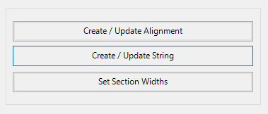
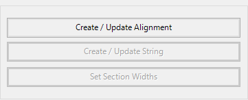 Step 3: Creating the Horizontal Geometry |
|||||||||||||||||||||||||||||||||||||||
| Create/Update Alignment | Click to generate an Alignment for the cul-de-sac based on the displayed cul-de-sac design parameters and connection details defined
on the left of the form. This will create an Alignment connected to the selected Road at the specified connection point at the start and end of the cul-de-sac alignment.
Note: The initial display and label style applied (when the alignment is created) is set from the If the alignment is not appearing as desired, simply change the parameters defining the horizontal geometry and click on the Create/Update Alignment button again to recreate the alignment. |
||||||||||||||||||||||||||||||||||||||
|
|
|||||||||||||||||||||||||||||||||||||||
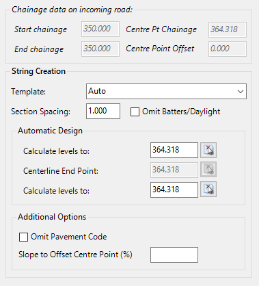
| String Creation | Clicking
theCreate/Update Alignment button will activate the String Creation tools and
update the information in the fields for the chainage data on the incoming road.
Until a valid Alignment design is created, this side of the form will be
inaccessible and greyed out.
|
||||||||||||||||||||||||||||||||||||||
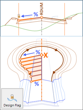
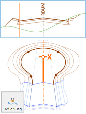
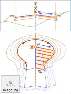
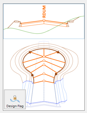
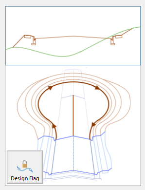
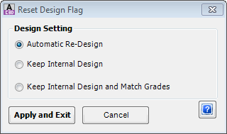
| Reset Design Flag | The software will automatically design the IPs to smoothly transition the cul-de-sac profile between the set IPs. Reset Design Flag enables the designer to change the controls between the set IPs. Upon selecting the command the following form is displayed:
|
||||||||||||||||||||||||||||||||||||||
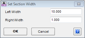
| Set Section Widths | This enables the user to set the display widths left and right of the alignment, which impacts the Cross Section View in the Vertical Grading Editor.
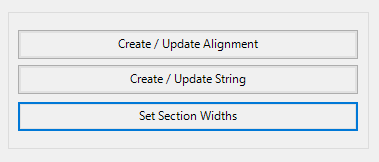 Upon selecting the command the following form is displayed:
|
||||||||||||||||||||||||||||||||||||||
| Show VGE on Close |
Click this check box on to display the Vertical Grading Editor upon closing this
form. This will enable immediate review/editing of the cul-de-sac string
design.
Click here for more information regarding design using the |
||||||||||||||||||||||||||||||||||||||
| Close | Click here to exit the form, with or without having created a Cul-de-sac in the software. | ||||||||||||||||||||||||||||||||||||||
 |
Click on this button to enable zooming and panning in the drawing window using the middle mouse scroll button. Press [enter] or [esc] to cancel the zoom/pan and return to the form. | ||||||||||||||||||||||||||||||||||||||