Corridor Settings
Icon: |
Introduction
When the corridor is created, the user has some controls over how target mapping is applied, as well as the layout of assemblies in the drawing and whether alignments a placed in a Site.
Details
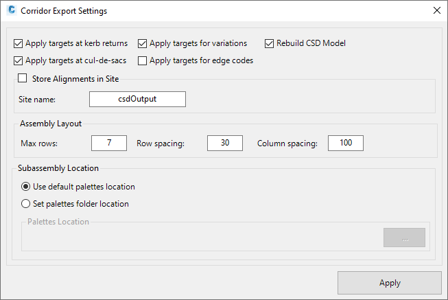
Upon selecting the command the following form is displayed:
|
|
|
|
Apply Targets at kerb returns |
Tick on to use Target Mapping in the corridor for the curb return 'pavement' (the DUM code on the curb return). If ticket on, target mapping for the width and elevation will be applied to the edge of the main road and C.L. of the side road. If unticked, parameter overrides will be applied to set the pavement width and elevation of the curb 'pavement' code. |
|
Apply Targets at cul-de-sacs |
Tick on to use Target Mapping in the corridor for the cul-de-sac 'pavement' (the DUM code on the curb return). If ticket on, target mapping for the width and elevation will be applied to the C.L. of the incoming main road . If unticked, parameter overrides will be applied to set the pavement width and elevation of the cul-de-sac 'pavement' code. |
|
Apply Targets for variations |
Tick on to use Target Mapping in the corridor when Variations are applied to the string (Match Code to Alignment or Match Code to String). If unticked, parameter overrides will be applied to set the pavement width and elevation. |
|
Apply Targets for edge codes |
Alignments and profiles will be created at the road edge (Intersection Match-in code as set in the Active Drawing Settings) of Road Strings. Tick on to use Target Mapping to set the road edge code width and elevation. If unticked, parameter overrides will be applied to set the road edge width and elevation |
|
Rebuild CSD Model |
Tick on to rebuild all models before creating the corridors. Recommended. Out of date models will result in unexpected corridor outputs. |
|
Store Alignment in Site |
Tick on for alignments created by Civil Site Design to be placed in a Site. |
|
Site name |
Type in the name of the Site the alignments are created in |
|
Assembly Layout |
When the assemblies are created, they are created in a grid in the drawing |
|
Max Rows |
Type in the number of rows in a grid of assemblies. After this number of rows, a new row starts |
|
Row Spacing |
Distance between rows |
|
Column Spacing |
Distance between columns |
|
Subassembly Location |
Sets where subassemblies are stored. |
|
Use default palettes location |
The default location for Civil 3D is used to locate subassemblies for application in Civil Site Design. |
|
Set palettes folder location |
Toggle this option to locate subassemblies in a user specified location. |
|
Palettes location |
The path to the specified location of the subassemblies will be shown here. Use the ... button to select the folder. |
|
Apply |
Save and exit |