Create/Edit Section Templates
Icon: |
  |
Introduction
Civil Site Design (and
Stringer Topo)
includes its own Template (Assembly) creator. This is a simple and
intuitive interface which provides designers with the capacity to create
any type of typical cross section shape required.
These typical cross sections (also known as Templates or Assemblies)
can be created and/or edited via the Create/Edit Templates command. Templates
are applied to any String to generate design cross sections.
The creation of appropriate Templates is integral to the String design
process.
About the Form - General Features and Display Controls
The name of the current Template is shown at the top of the form. The
form is split up into functional components, in the following general
arrangement:
- Top of the form, left - Data Editing in tabular format:
this enables adjustment of offsets (horizontally and vertically) for
created subassembly components
- Top, to the right - Collection of command buttons: navigate to
different Templates as well as provide edits in the Data Edit form.
- Mid-Right- Create/Edit Sections: Main creation/editing tools for
daylighting, line components and kerb components, incorporating subgrades.
- Bottom of the form, right (Define Subgrade Conditions allowing
for new labels inserted into the cross section)
- Bottom of the form, left (as well as navigation panels on the right
and top right): controls the visual representation of Template design
data being assembled as well as a display of the template as it is
constructed
Naming Templates - Ground Rules
Special Note: Template Naming Conventions. DO NOT use commas
in the name of the Template or !@#$%^&*() characters.
Creating Templates - Fundamental Procedure
It is recommended that the following commands are used to create and
edit a basic Template:
- Create Template sections and batters, or edit the applied subgrade
using the command buttons on the form.
- Edit the horizontal and vertical offset parameters using the Data
Editing Form:
- The left side (pink) represents 'segments', or subassembly
links, progressively designed working from the centreline outwards
to the left. Each Leg is a line segment (Section) in
the assembly
- The right side (green) represents 'segments', or subassembly
links, progressively designed working from the centreline outwards
to the right. Each Leg is a line segment (Section)
in the assembly
- Adjustments made to offset, slope, vertical distance or label
will have an immediate impact on the Template view and on any
Road (or Road Object) that refers to the Template.
Saving Templates - Public and Local
Designers are able to create 'Public' templates and 'Local' templates. The
differences are:
- 'Local' Template
- saved to the current project ONLY
- is not available in any other project
- can be used directly on any Road or road object created
- 'Public' Template
- saved to the CSD Settings location (the Settings location can
be adjusted using the
 Set Settings
Path command)
Set Settings
Path command)
- can be viewed and copied locally to ANY project
- cannot be used directly in a local project (a Local Copy would
need to be made)
About Template Subgrade (Pavement) Layers
The Template Editor stores a list of Code pairs and assigns Subgrade
(Pavement) Layers between each Code pair.
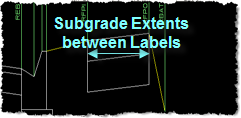
For instance, when you create a code named LEB next to the centreline
(C.L.), the subgrade layers you apply are applied between the two codes
C.L. and LEB only.
When you remove a Code out of the Template or change the name of a Code
be aware that you will also have to account for the new/changed Code pairs
that result. It will be required to use the subgrade editing
options on this form to re-establish the appropriate subgrade between
the remaining code pairs.
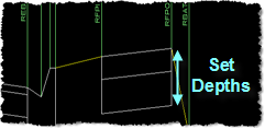
About Template Subgrade (Pavement) Layers - Advanced Controls
By default, subgrade (pavement) layers are defined between code pairs
(with kerbs being a special case) with layers parallel to the design surface
and stopping at the extents of the codes.
Advanced settings in the form enable designers to extend the subgrade
layers beyond the codes, set a slope on the layer and set layers to extend
down to the surface instead of maintaining a constant depth. Designers
are also able to set a different slope on the bottom layer of the subgrade,
different to the top layer. Below are some sketches depicting
the changes that can be applied to the subgrade:
| No Layer Controls |
Extension |
Extend to Design |
End Slopes |
Match Layer to Surface |
 |
 |
 |
 |
 |
About Code Naming Conventions - CRITICAL INFORMATION
When creating codes in the Data Editing form (This does NOT
APPLY when creating data using the section/kerb creation forms) it
is vital that the designer:
- PREFIX codes on left with 'L'
- PREFIX codes on the right with 'R'
In general the following is recommended:
- Provide a code name to each segment created (this is REQUIRED and
the software will generate an error message to advise that label/s
are missing from the template section/s.
- Use a CONSISTENT code to define the connection point for kerb returns,
cul-de-sacs and knuckles. This connection point label is
used in creating these objects as defined in the Active Drawing
Settings.
About Creating Kerb Returns, Cul-de-sacs or Roundabout 'Templates'
The software automatically stretches the road pavement of the Kerb,
Cul-de-sac and Roundabout objects in order to match up the intersections. In
order for this to occur the designer MUST define these templates with
an LDUM or RDUM (depending if it is on the left or right side of the centerline)
code - the software stretches this code (including subgrade layers) out
to match up at the intersections.
When a Template is applied
When a Template is applied to the feature, the software stretches the
label LDUM or RDUM (pending the direction of the alignments) to match
up the intersection or, in the case of the Roundabout, to match to the
outer edge of the circulating carriageway alignment.
If this label is missing, there will be no 'pavement' created to match
out to the rest of the intersection.
Kerb Return and Cul-de-sacs - When an 'Auto' Template is Created
When creating Kerb Returns or Cul-de-sacs, the designer is able to set
the template to 'Auto' - in this case the software builds the cross section
automatically be reading the road sections at the start/end of these alignments.
In this event, the software does not automatically apply any subgrade
to the design but DOES allow a 'subgrade template' to be applied.
Accordingly the designer needs to allow for the subgrades to be inserted. Additionally,
the coding for the alignment is not set to C.L. - it is set to the Connection
Point Code (as defined in the Active Drawing Settings form).
In order to accommodate for this, a 'Road' template should be created
and include an allowance for the event where there is pavement working
outwards from the Connection Point Code.
When 'Auto' is applied to the feature, the software creates a label
pair between the Connection Point Code and RDUM/LDUM (pending the direction
of the alignments) to match up the intersection.
Use the Set Subgrade on Insert command to create these label
pairs in the Template being applied.
Creating Knuckles - Automatic 'stretching' of the Road Pavement
When a Knuckle is created and the option is selected to extend the Road
pavement out to the knuckle alignment, an additional label called LNUK/RNUK
(pending which side of the road) is used. This label is automatically
created AFTER the Connection Point Code.
In order for a subgrade to be assigned to this section of pavement,
the designer must create Subgrade Layer pairs for the Connection Point
Codes and LNUK/RNUK labels (for left and right sides).
Set Subgrade - Using * Wildcard
The Set Subgrade control allows users to type in a pair of codes to apply
subgrade section layers to. Wildcards are supported for both of these
codes.
This results in the software searching for codes matching the input (eg:
adding LE* would include all Codes that start with LE, such as LEB, LETW,
LEG, etc.)
It is highly recommended to add wildcard controls on code pairs after
first establishing all specific subgrade behaviours for any code pairs
Wildcard entries will apply to all code pairs that are included in the
wildcard addition and weren't already previously managed.
Details
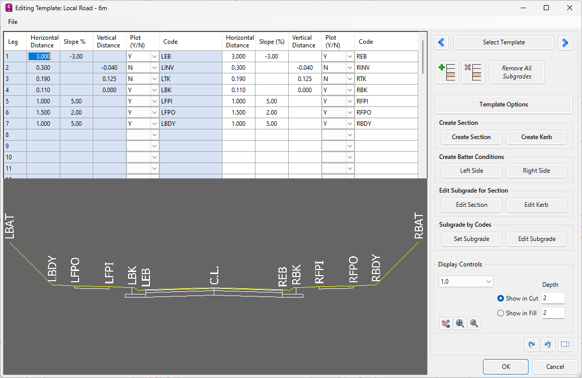
Upon clicking the Create/Edit Section command the Template Editor is
displayed:
To navigate to particular commands of the Template Editor, click on
a command button or view window from the image below:
|
|
File
|
Opens the file menu, options include:
|
|
New Template (Local)
|
Makes a
new Local Template. Designer is required to
type in a name for the new template and OK.
|
|
New Template (Public)
|
Makes a
new Public Template. Designer is required to
type in a name for the new public template and OK.
|
|
Copy Template (Local)
|
Copies the
current Template to the LOCAL project. Designer
provides a name for the locally copied template.
|
|
Copy Template (Public)
|
Copies the
current Template to the PUBLIC template library. Designer
provides a name for the publicly copied template.
|
| Data
Edit Tabular Form |
This form enables editing of the tabular
data describing the top links of the Template:
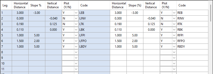
The left side (blue) represents 'segments', or subassembly
links, progressively designed working from the centreline
outwards to the left. Each Leg is a line segment (Section)
in the assembly
The right side (white) represents 'segments', or subassembly
links, progressively designed working from the centreline
outwards to the right. Each Leg is a line segment (Section)
in the assembly
Adjustments made to horizontal distance, slope, vertical
distance or code will have an immediate impact on the
Template view and on any Road (or Road Object) that refers
to the Template.
Each Row of data correlates to a Leg/Section in the
Template. For each line of data:
|
| Leg |
The Leg
number is the Section/Segment number, working from the
centerline outward. Leg 1 connects to Leg 2,
Leg 2 to Leg 3, and so on |
| Horizontal
Distance |
This is
the horizontal width of the Section |
| Slope
% |
Type in
the slope in % - leave blank if it is required to set
a vertical distance.
Convention is:
- Left Side: + value is a clockwise rotation
- Right Side: + value is a counter-clockwise rotation
|
| Vertical
Distance |
Type in
the vertical distance - leave blank if it is required
to set a slope. + value is a vertical distance up. |
| Plot
(Y/N) |
Use pick
list to set Yes or No. Determines if the label information
is displayed in the Template viewer. |
| Code |
Provide
a code name for the end of the Section. Codes act as the
points on the cross section. |
|
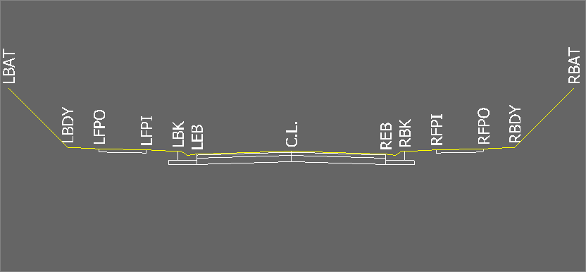
| Template Viewer |
The Template Viewer provides a 'live' display of the design cross
section.
|
| |
|
|
[Right Click Menu]
|
Right click in the Template Viewer to access menu commands |
| |
|
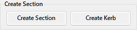
Create Section
|
Add a new pavement section to the current template.
See Create Section.
|
|
Create Kerb
|
Add a new kerb section to the current template. See
Create Kerb.
|
|
Edit Section
|
Edits the subgrade for the Section based on the right
click location. See
Edit Subgrade for
Section.
|
|
Edit Kerb
|
Edits the subgrade for the Kerb based on the right click
location. See Edit Kerb.
|
|
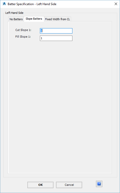
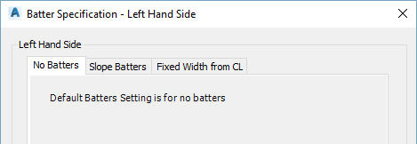
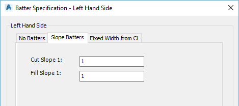
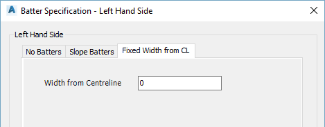
Batter (Daylight) Left
|
Assign batter/daylighting conditions on the left side of the assembly.
|
|
Batter (Daylight) Right
|
Assign batter/daylighting conditions on the
right side of the assembly.
|
|
Template Options
|
Open the Template Option sub-menu:
|
|
|
|
Copy To Left
|
This command
takes all the data entries on the right side and 'mirrors'
them onto the left side. A warning message
will display if data on the right will be deleted
|
|
Copy To Right
|
This command
takes all the data entries on the left side and 'mirrors'
them onto the right side. A warning message
will display if data on the right will be deleted
|
|
Delete Left
|
Deletes
all entries on the left hand side of the Data Edit
form
|
|
Delete Right
|
Deletes
all entries on the right hand side of the Data Edit
form.
|
|
|
| Select Template |
Click on this button to select the Template
to view/edit from a list:
|
| |
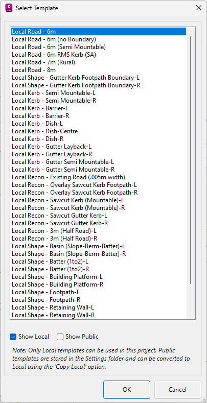
Pick the required Template.
|
|
Show Local
|
Toggle on/off to show the local templates in the template
list. ON by default.
|
|
Show Public
|
Toggle on/off to show public templates in the template list.
OFF by default.
|
| OK |
Apply and
exit. |
| Cancel |
Exit the
form without selecting a different Template. |
Note: The name of the current Template is displayed
at the top of the Template Editor.
|
 Prev
Prev |
Click on this button to cycle backwards
through the list of available Templates. |
 Next
Next |
Click on this button to cycle forwards
through the list of available Templates. |
 Insert Line
|
This is used to insert an entire Section
(Leg) in between other Sections within the Template: |
| |
The process is:
- Highlight the line to insert above/before
- Click on the Insert Line button
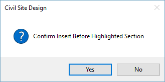
|
| Yes |
Click to
insert the segment. |
| No |
Click to
exit without inserting the segment. |
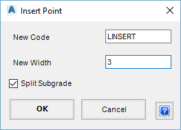
After clicking Yes and following form is displayed:
|
| New Label |
Give the
new section a name. |
| New Width |
Specify
the width of the new section. |
| Split
subgrade |
Tick on
so when a new section is created the current subgrade
remains on both the existing and new sections and is not
deleted |
| OK |
Apply and
exit. |
| Cancel |
Click to
exit without inserting the segment. |
|
 Remove Line
|
This is used to delete an entire Section
(Leg) from the Template. |
| |
The process is:
- Highlight the Section/Leg to delete
- Click on the Remove Line button
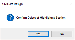 |
| Yes |
Click to
delete the highlighted section. |
| No |
Click to
exit without deleting the segment. |
|
| Remove
All Subgrades |
Click to delete all existing subgrades
in the template being viewed. |
| Template Options |
Upon selecting the command the following
form is displayed:
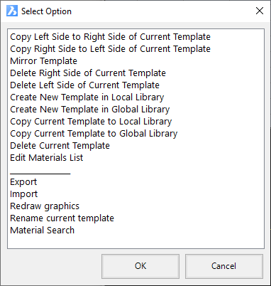
|
| Copy
Left Side to Right Side of Current Template |
This command
takes all the data entries on the left side and 'mirrors'
them onto the right side. A warning message
will display if data on the right will be deleted. |
| Copy
Right Side to Left Side of Current Template |
This command
takes all the data entries on the right side and 'mirrors'
them onto the left side. A warning message
will display if data on the left will be deleted. |
| Mirror
Template |
This command
swaps the data entries between the left and right sides.
For instance, all left side values will become right side
values and vice-versa. |
| Delete
Right Side of Current Template |
Deletes
all entries on the right hand side of the Data Edit
form. |
| Delete
Left Side of Current Template |
Deletes
all entries on the left hand side of the Data Edit
form. |
| Create
New Template in Local Library |
Makes a
new Local Template. Designer is required to
type in a name for the new template and OK. |
| Create
New Template in Public Library |
Makes a
new Public Template. Designer is required to
type in a name for the new public template and OK. |
| Copy
Current Template to Local Library |
Copies the
current Template to the LOCAL project. Designer
provides a name for the locally copied template. |
| Copy
Current Template to Public Library |
Copies the
current Template to the PUBLIC template library. Designer
provides a name for the publicly copied template. |
| Delete
Current Template |
Deletes
the currently selected Template from the library. |
| Edit
Materials List |
Opens the
material list to type in new material names or edit the
names of existing materials. These can then be applied
to the subgrade layers.
Upon selecting the command the following form is displayed:
|
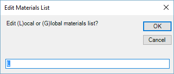
Set the value to L to edit local materials or
G
to edit materials stored in the Settings folder
(for reuse in future jobs). Following
selection and clicking OK the following form displays:
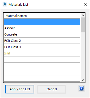
|
| Material
Names |
To
edit an existing material, click the name to be
changed and type a new name to overwrite it. A
new material can be added by clicking an empty
cell and entering a new name. |
| Apply
and Exit |
Save
changes and exit the form. |
| Cancel |
Exit
the form without changing any data. |
Special Note: Template Naming Conventions.
It is recommended that users do NOT put full stops
OR commas in the name of the Template or use !@#$%^&*()
characters.
|
| Export |
Use this
command to export a template as a file. |
| Import |
Use
this command to import a template from a file.
The option to import the Subgrade Only
is also available.
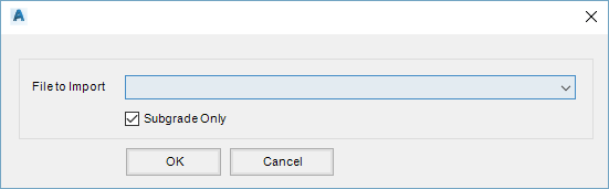
|
| File
to Import |
Chose
the file to import from the drop-down list. |
| Subgrade
Only |
Tick
this box to import the subgrade only. |
| OK |
Import
the selected file. |
| Cancel |
Exit
the form without importing any files. |
|
| Redraw
graphics |
Click to
refresh the graphic in the Template Editor. |
|
Rename current template
|
Rename the current template.
Note: The user will be warned to closed
all Design Data forms to make sure that changed template names
are updated correctly.
|
| Material
Search |
This command
enables mass editing of a selected material, across all
Templates.
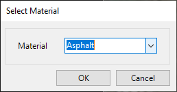 |
| Material
Picklist |
Select
a material to review. |
| OK |
Edit
the material |
| Cancel |
Cancel. |
After selecting a material the following form will display:
 |
| Type |
Reportable
Item only. Local (for current project)
or Public (stored in the CSD Settings folder) |
| Template |
Reportable
Item only. Template containing the
material |
| Code1 |
Reportable
Item only. Located between Code 1 and
Code 2 |
| Code
2 |
Reportable
Item only. Located between Code 1 and
Code 2 |
| Layer |
Reportable
Item only. Displays the layer number
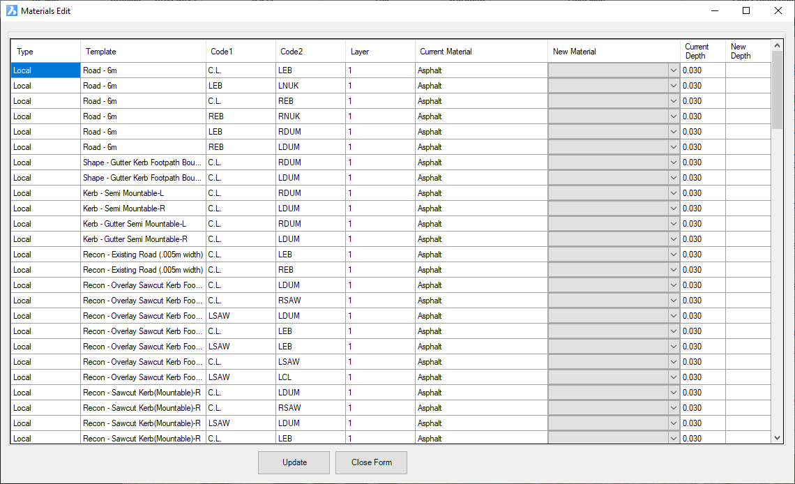
(from top to bottom) |
| Current
Material |
Reportable
Item only. Lists the current material |
| New
Material |
Pick
to change to a different Material. |
| Current
Depth |
Reportable
Item only. Lists the current depth
of the material layer. |
| New
Depth |
Type
in a new (changed) depth for the layer on the
template. |
|
| Update |
Apply all
the edits (New Material and New Depth). |
| Close
form |
Exit without
applying changes. |
|
| Create
Section |
Allows the designer
to create new sections and kerbs |
| |
Use these commands to add a new pavement section or
kerb to the current template.
|
| Create Section |
Click on
the button to start this command. On exit a new Section
will be created and connected to the last leg of the Template
(before the batter/daylighting).
On start of this command the following form is displayed:
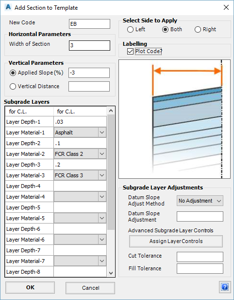
Note: the graphic window will update on hover
over the different inputs.
|
| New
Code |
Type
in a name for the new label to be created.
Note: There is no need to prefix the
label here with 'L' or 'R'.
|
| Width
of Section |
Type
in the width required for this new section |
| Applied
Slope (%) |
Toggle
this method on if desired and type in a value
(in percentage) for the slope to be applied to
the section. Convention is as follows:
- Zero: flat
- Left Side: + value up and - value down
- Right Side: + value up and - value down
|
| Vertical
Distance |
Toggle
this method on if desired and type in a value
(+ is an upward change) |
| Subgrade
Layers |
Set
up to 10 subgrade layers. These correlate
to material thicknesses. After specifying
a depth the user then sets a Material.
| Layer Depth-1 |
Thickness of
layer 1 of the subgrade |
| Layer Material-1 |
Use the pick
list to assign a material to the layer
depth above - the materials are set in
the Material List. |
|
| Select
Side to Apply |
Toggle
to chose which side to apply the new section to:
| Left |
Create the new
segment on the left side |
| Both |
Create two segments
- one on the left and one on the right |
| Right |
Create the new
segment on the right side |
|
| Plot
Code |
Tick
on to show the label in the Template viewer |
| Subgrade
Layer Adjustments |
A range of command options
are available to make adjustments to the subgrade
layers so they are not a constant depth between
the two Labels. |
| Datum
Slope Adjust Method |
The
bottom layer of the subgrade can have the slope
adjusted so it is different to the top surface
slope. Options are:
- Use Value: The value specified in the Datum
Slope Adjustment is used for the slope of
the bottom layer of the subgrade
- Add Value: The value specified in the Datum
Slope Adjustment is ADDED to the slope of
the top surface and this slope is applied
to the bottom layer of the subgrade
- No Adjustment: The value specified in the
Datum Slope Adjustment is ignored.
|
| Datum
Slope Adjustment |
Type
in a % slope adjustment for the DATUM line - whether
it is Relative or Absolute depends on the Datum
Slope Adjust Method specified. |
|
Assign
Layer Controls
|
Click
on this button to assign advanced controls on
the behaviour of the subgrade layers.
Upon selecting the command the following form
is displayed:
Note: the graphic window will update
on hover over the different inputs
|
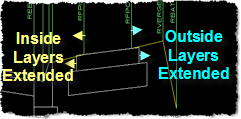
| Outside
Top Extension |
This option
extends the subgrade horizontally beyond
the Outer Label (working outwards from
the centreline).
Type in a value: a positive value moves
the top edge further out, away from the
centreline.
|
| Inside
Top Extension |
This option
extends the subgrade horizontally beyond
the Inner Label (working inwards toward
the Centreline).
Type in a value: a positive value moves
the top edge further in, towards from
the centreline.
No Layer Controls:
Layer Controls Applied - Extension:
|
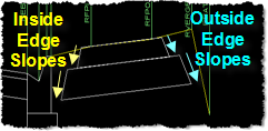
| Outside
End Slope (1 in) |
This option
enables the end slope of the subgrade
to be changed from vertical.
Type in a value - the convention is
1: (Rise:Run). (e.g. typing in 1 would
imply 1:1 slope, or 45%)
|
| Inside
End Slope (1 in) |
This option
enables the end slope of the subgrade
to be changed from vertical.
Type in a value - the convention is
1: (Rise:Run). (e.g. typing in 1 would
imply 1:1 slope, or 45%)
No Layer Controls:
Layer Controls Applied - End Slopes:
|
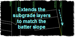
| Outside
Extend to Design |
This option
enables the outside edge of the layers
to extend out to the design edge. The
routine assumes extension immediately
to the batters (last label before the
batters). The top layer will not extend
- it is assumed that the outside edge
layer is where the extension is calculated
from.
This option requires the Outside
Top Extension and Outside End Slope
values to be set to zero (off).
Use the Pick List. Options are:
- No Extension: doesn't apply
any extension
- Fill Only: only applies
the extension in fill conditions (checks
the bottom of the layer at the end)
- Cut Only: only applies the
extension in cut conditions (checks
the bottom of the layer at the end)
- Cut and Fill: tries to apply
the extension whether in cut or fill
- in the event that no solution is
found it doesn't apply any extension
No Layer Controls:
Layer Controls Applied - Extend to
Design:
|
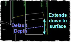
| Match
Depth to Surface |
Set to Yes
or No. If set to Yes
then the depth of the chosen layer will
extend to the surface up to the value
set in Maximum Extra Depth.
No Layer Controls:
Layer Controls Applied - Match Depth
to Surface:
|
| Minimum
Thickness |
Sets the minimum
thickness of the layer in cut situations.
Set to zero to allow the subgrade layer
to be removed in cut.
Set a value for the minimum allowable depth. |
| Maximum
Extra Depth |
Sets the extra
depth (in addition to the default depth)
to extend the sampled surface in fill
- if the depth extends beyond this value
the layer will adopt the maximum depth
(default depth plus Maximum Extra Depth
value).
Set to a large value (e.g. 100) to always
extend to the surface.
Set a value for the maximum extra layer
thickness in fill situations. |
| Alternate
Material for Extra Depth |
Not implemented |
| Description |
Set a description
for the layer adjustment |
| Ignore
Outside Extension |
This input is
associated with the Outside Top Extension
and Outside End Slope inputs.
By default, the start width of the layer
is set by the preceding (higher) layer
width. Set to Yes to measure
the extension from the outside Code (zero
additional width) |
| Ignore
Inside Extension |
This input is
associated with the Inside Top Extension
and Inside End Slope inputs.
By default, the start width of the layer
is set by the preceding (higher) layer
width. Set to Yes to measure
the extension from the outside Code (zero
additional width) |
| Thickness
from Existing |
The depth of
the layer can be set based on the depth
of the sampled surface. Options
are:
- No: do not adjust layer depth based on
a surface
- Inner: find the surface elevation at
the inside code and use that for the layer
depth
- Outer: find the surface elevation at
the outside code and use that for the
layer depth
- Both: find the surface elevation at the
outside and inside code and use this to
set a lineearly changing depth between
the elevation at the inside to the elevation
at the outside
Note: this value will not be applied
if the layer would otherwise have zero
or negative thickness..
|
| Description |
Set a description
for the layer adjustment |
| Apply and
Exit |
Apply the additional
layer controls and exit the form. |
| Cancel |
Exit the form
without saving any changes. |
|
| Cut
Tolerance |
Type
in a tolerance value - the subgrade rules set
in the Assign Layer Controls will be applied
if the tolerance is exceeded in cut. Leave
this blank to apply immediately in cut. |
| Fill
Tolerance |
Type
in a tolerance value - the subgrade rules set
in the Assign Layer Controls will be applied
if the tolerance is exceeded in fill. Leave
this blank to apply immediately in fill. |
| OK |
Create
the section and exit the form. |
| Cancel |
Exit
the form without creating a new section. |
|
|
Create
Kerb |
Click on
the button to start this command. On exit a new kerb section
(subassembly component) will be created and connected
to the previous leg of the Template (before the daylighting).
Only use this command to create kerb sections.
On start of this command the following form is displayed:
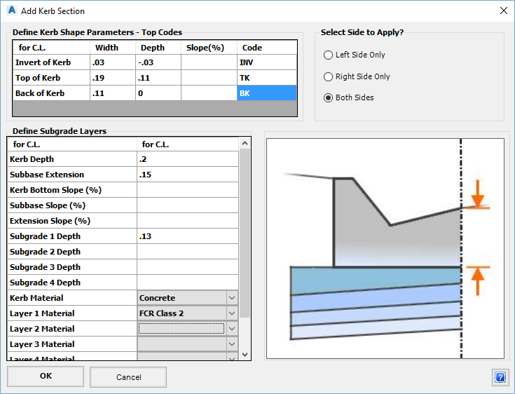
Note: the graphic window will update
on hover over the different inputs
|
| Define Kerb Shape Parameters
- Top Codes |
Simple geometry tools to
set out the top of the kerb line. |
| Invert
of Kerb |
Type
in (relative to the connection label, which is
usually the edge of bitumen, for example the green
line in the Detail Sketch):
- Width: Width to the flow line
- Depth: Type in a vertical distance
or leave blank if defined by Slope
- Slope (%): Type in a slope value
in % or leave blank if defined by Depth
- Code: Type in a Code
|
| Top
of Kerb |
Type
in (relative to the Flow Line label):
- Width: Width to the Face of Kerb
- Depth: Type in a vertical distance
or leave blank if defined by Slope
- Slope (%): Type in a slope value
in % or leave blank if defined by Depth
- Code: Type in a Code
|
| Back
of Kerb |
Type
in (relative to the Top Point label):
- Width: Width for the Top of Kerb
- Depth: Type in a vertical distance
or leave blank if defined by Slope
- Slope (%): Type in a slope value
in % or leave blank if defined by Depth
- Code: Type in a Code
|
| Define
Subgrade Layers |
Used to setup the subgrade
below the kerb. |
| Kerb
Depth |
Depth
of the kerb, measured from the lip |
| Subbase
Extension |
Distance
to extend behind the Back Point with the subgrade |
| Kerb
Bottom Slope (%) |
Type
in for a slope (%) along the base of the kerb |
| Subbase
Slope (%) |
Type
in for a slope (%) along the datum |
| Extension
Slope (%) |
Type
in for a slope (%) for the extended part of the
subgrade behind the Back Point |
| Subgrade
Depth 1 |
Subgrade
Layer 1 thickness below the kerb |
| Subgrade
Depth 2 |
Subgrade
Layer 2 thickness below the kerb |
| Subgrade
Depth 3 |
Subgrade
Layer 3 thickness below the kerb |
| Subgrade
Depth 4 |
Subgrade
Layer 4 thickness below the kerb |
| Kerb
Material |
Use
the pick list to assign a material |
| Layer
1 Material |
Use
the pick list to assign a material to Depth 1 |
| Layer
2 Material |
Use
the pick list to assign a material to Depth 2 |
| Layer
3 Material |
Use
the pick list to assign a material to Depth 3 |
| Layer
4 Material |
Use
the pick list to assign a material to Depth 4 |
| Select Side to Apply |
Choose which side of the
Template to apply the new kerb. |
| Left
Side Only |
Create
the new kerb on the left side |
| Right
Side Only |
Create
the new kerb on the right side |
| Both
Sides |
Create
two kerbs - one on the left and one on the right |
| OK |
Create
the kerb subassembly and exit the form. |
| Cancel |
Exit
the form without creating a new kerb. |
|
|
| Create
Batter Conditions |
These commands enable
the user to assign batter/daylighting conditions on the left and
right sides of the assembly. |
| |
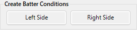
Click on Left Side to assign batter/daylight conditions
on the left side.
Click on Right Side to assign batter/daylight conditions
on the right side.
Upon selecting the command the following form is displayed with
the current Batter/Daylight Type displayed:
|
| Edit
Subgrade for Section |
The editing tools
have been provided to enable quick editing of subgrade depths
and other features of the selected section or kerb. |
| |
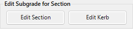
Use these commands to edit a pavement or kerb section.
|
| Edit
Section |
Use this
command to select a line in the Template Viewer and edit
the section.
After clicking Edit Section, the following is
displayed:
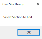
Click OK to proceed and select a section
to edit in the Template Viewer.
Upon making the selection the following form
is displayed:
|
|
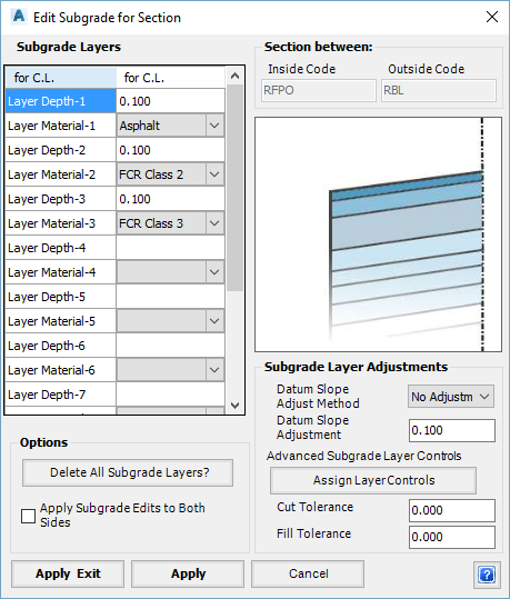
| Subgrade Layers |
See Subgrade
Layers |
| Options |
Set the edit method |
| Delete
All Subgrade Layers |
Click
on this button to remove the entire section |
| Apply
Subgrade Edits to Both Sides |
Toggle
this on to have the edits applied to both the
left and right sides |
| Subgrade Layer Adjustments |
See Subgrade
Layer Adjustments |
| Apply
and Exit |
Save
changes and exit the form. |
| Apply |
Save
changes. |
| Cancel |
Exit
the form without saving changes. |
|
|
Edit
Kerb |
Use this
command to select a line in the Template viewer representing
a part of the kerb to edit it.
After clicking Edit Kerb, the following is displayed:
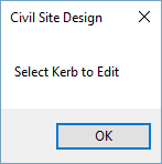
Click OK to proceed and select a part
of a kerb to edit in the Template Viewer.
Upon making the selection the following form
is displayed:
|
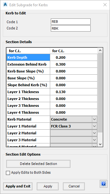
|
| Kerb to Edit |
Code 1 and Code 2 define
the line segment being edited |
| Code
1 |
Code
defining the section |
| Code
2 |
Code
defining the section |
| Section Details |
See Define
Subgrade Layers |
| Section Edit Options |
Set the edit method |
| Delete
Selected Section |
Click
on this button to remove the entire section |
| Apply
Edits to Both Sides |
Toggle
this on to have the edits applied to both the
left and right sides |
| Apply
and Exit |
Save
changes and exit the form. |
| Apply |
Save
changes. |
| Cancel |
Exit
the form without saving changes. |
|
|
| Subgrade
by Codes |
These commands have
the same function as Edit Section, however the section
to be edited is defined by entering/selecting codes instead of
clicking on it in the Template Viewer. |
| |
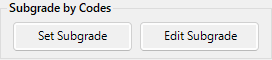
Use these commands to edit a subgrade section.
| Set
Subgrade |
Use this
command to edit a section by manually inputting the codes
which enclose the section.
After clicking Set Subgrade, the following is
displayed:
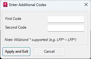
|
| First
Code |
Enter
the label defining the start of the section. |
| Second
Code |
Enter
the label defining the end of the section. |
| Apply
and Exit |
Click
to edit the subgrade for the section defined by
the codes. |
| Cancel |
Exit
the form without saving any changes.. |
After clicking Apply and Exit the following form
is displayed:
|
| Subgrade Layers |
See Subgrade
Layers |
| Options |
Set the edit method |
| Delete
All Subgrade Layers |
Click
on this button to remove the entire section |
| Apply
Subgrade Edits to Both Sides |
Toggle
this on to have the edits applied to both the
left and right sides |
| Subgrade Layer Adjustments |
See Subgrade
Layer Adjustments |
| Apply
and Exit |
Save
changes and exit the form. |
| Apply |
Save
changes. |
| Cancel |
Exit
the form without saving any changes. |
|
| Edit
Subgrade |
Same functionalities
as Set Subgrade, but the section is chosen by selecting
it from a list of codes.
After clicking Edit Subgrade, the following is
displayed:
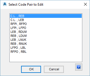
|
| Code
Pair |
Select
the section to be edited |
| OK |
Click
to edit the subgrade for the section defined by
the codes. |
| Cancel |
Exit
the form without saving any changes.. |
After clicking OK the following form is displayed:
See Edit Subgrade
|
|
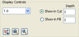
| Display
Controls |
The View Display Controls
Panel to the right controls the Template Viewer window, with the
exception of showing the extents of the daylighting. |
| |
|
 Redo and Undo
 |
Click on the left icon to progressively
REDO undone commands or click on the left icon to progressively
UNDO commands undertaken whilst in the Create/Edit Templates
form. |
| OK |
Apply and exit. |
| Cancel |
Exit the form without saving changes. |
 Zoom Scale