Multi Object Setout
Icon:
![]()
![]()
![]()
Introduction
Use this command to set out the design of any and all Strings created - this includes roads, kerb returns, cul-de-sacs, general strings, etc. The user is able to set out multiple strings at once.
The set out process facilitates the following documentation outputs:
-
display of point information in the drawing consisting of a marker and (user definable) text
-
display of a set out table in the drawing, with user control over the columns of information and the drafting presentation - tables are created as AutoCAD Table objects and can be udpated simply by re-running this command and clicking on Create Setout
-
creation of a points file output (optionally to .csv format for immediate opening and editing in Excel)
-
creation of Civil 3D COGO points directly in the drawing (Civil 3D version only)
It is anticipated that most users will establish the settings they like for the set out output and save this as a Style for re-use on other projects.
This is a multi tabbed form, including the following:
-
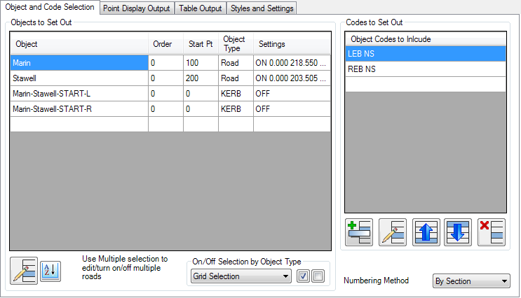
Object and Code Selection
-
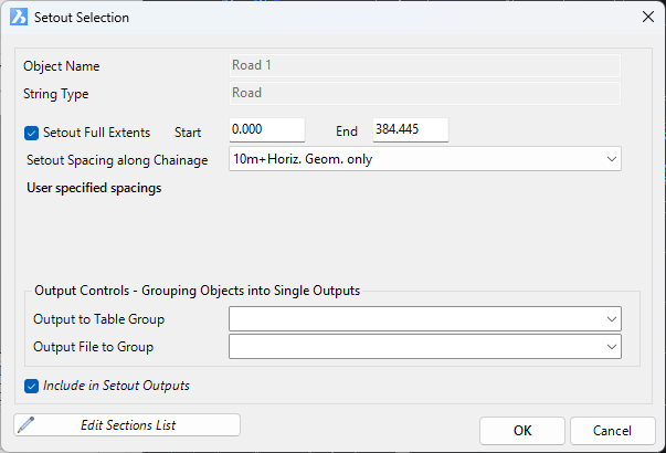
Select the Strings to include in the setout, including start point number, order of setout and sampling for setout
-
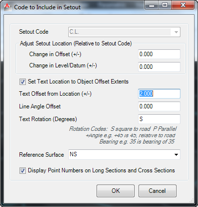
Select the Codes to include in the setout for every string
-
-
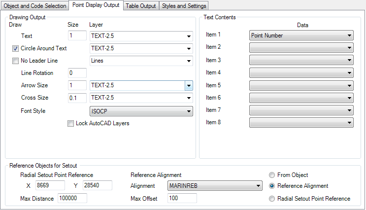
Point Display Output (Simple CAD Objects)
-
Control the display output - size of marker, size and style of text and layer output
-
Manage the text contents - the user is able to include up to 8 properties to include in the textual output. Each Item/property selected to be included is appended to the text string, in order, with a space between each Item/property selected (eg: show Point Number, Chainage and Offset by picking these Items in order in the Items list)
-
-
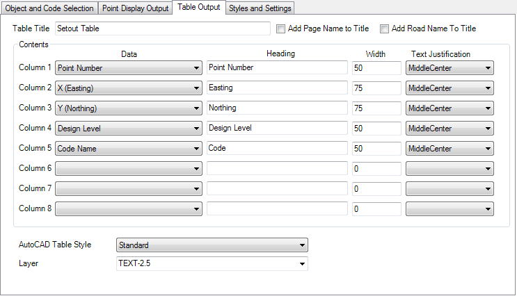
Table Output
-
Control the display output - pick the AutoCAD Table Style, layer, column widths and text justification for the table
-
Manage the table contents - the user is able to include up to 8 columns of information in the table - the user picks the Data to show in each column and types a Heading for the column
-
-
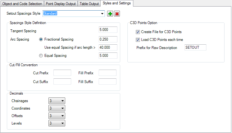
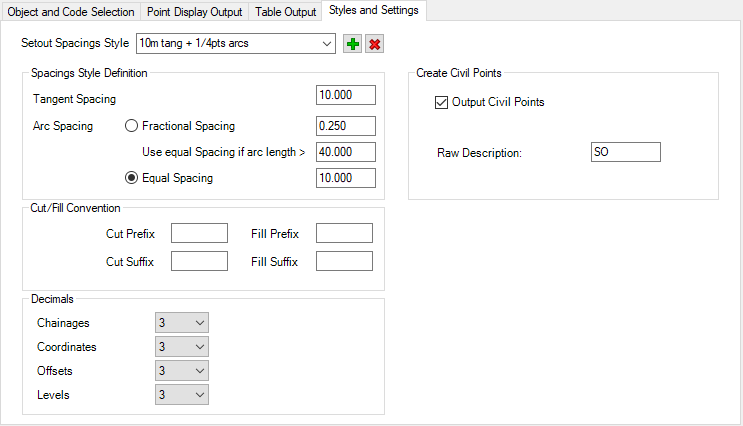
Styles and Settings
-
Establish user defined section sampling for setout - standard spacings and fractional spacings on curves
-
Establish cut/fill prefix and suffix to apply when cut/fill text is displayed
-
Tick on options to generate Civil 3D COGO Point output
-
The Output Controls down the bottom allow the user to pick what is included in the output - points in the drawing, tables and/or point file/s.
Users can configure different setout outcomes - the software allows each setout configuration to be named and other setout configurations can be made in the one project. This is envisaged to be used to quickly separate setout controls for roads, kerb returns and cul-de-sacs.
Point numbers are stored by the software for each String and are not re-used across Strings in a setout.
About Civil 3D Points Output (For Civil 3D Users)
-
Users can optionally select to create Civil 3D COGO Points as part of the output
-
All points created from this form will have a suffix in the Raw Description containing the Code of the point (eg: C.L., LEB, REB) - use the option to assign a Raw Description Prefix to put static text before the Code
-
There is no removal of previous points by the software before adding the points from the Create Setout command - if there are 'extra' points in the drawing these must be removed by the user before running the command.
-
There is no check of what is a software generated point and what is otherwise a Civil 3D point - the decision to overwrite or renumber points is handled entirely by Civil 3D - the user is prompted when duplicate point numbers are detected to take an action.
-
It is recommended to delete COGO points generated from the setout before redoing the SETOUT output
-
The software will renumber points using the Start Point number assigned to each string, from the start of the string to the end of the string. If no Start Point number is assigned or it has already been used by a previous string, the numbering will be assigned based on the Order of strings in the setout. If no Order is specified, the order of numbering will be based alphabetically on the String object name.
About CSD Points Output (For non-Civil 3D Users)
-
Users can optionally select to create CSD COGO Points as part of the output
Details
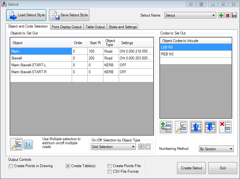
Upon selecting the command the first time, the user will be prompted to name the Setout. Upon naming the Setout, the following form is displayed:
|
|
|||||||||||||||||||||||||||||||||||||||||||||||||||||||||||||||||||||||||||||||||||||
| Load Setout Style | Load a setout style. This allows
quick establishment of required setouts - pre-set the codes to
setout, numbering method, setout to the drawing and external files,
point display in the drawing and table display in the drawing. Upon clicking this button a form displays listing all the saved Styles. Select a style and click OK to load it. Note: Styles are saved to the CSD Settings Folder. |
||||||||||||||||||||||||||||||||||||||||||||||||||||||||||||||||||||||||||||||||||||
| Save Setout Style | Save the current setout configuration as a setout style. A form will display to provide a name for the saved setout style. | ||||||||||||||||||||||||||||||||||||||||||||||||||||||||||||||||||||||||||||||||||||
| Setout Name | Select the named Setout to work with. | ||||||||||||||||||||||||||||||||||||||||||||||||||||||||||||||||||||||||||||||||||||
| Add New | Create a new named Setout configuration. A form will display to provide a name for the new named Setout. | ||||||||||||||||||||||||||||||||||||||||||||||||||||||||||||||||||||||||||||||||||||
| Delete Current | Delete the current named Setout configuration | ||||||||||||||||||||||||||||||||||||||||||||||||||||||||||||||||||||||||||||||||||||
| Save | Save the current named Setout configuration | ||||||||||||||||||||||||||||||||||||||||||||||||||||||||||||||||||||||||||||||||||||
| Multiple Tabs | Establishes how to apply the setout - what strings/codes to setout and how to display the information. | ||||||||||||||||||||||||||||||||||||||||||||||||||||||||||||||||||||||||||||||||||||
| Object and Code Selection |
|
||||||||||||||||||||||||||||||||||||||||||||||||||||||||||||||||||||||||||||||||||||
| Point Display Output |
|
||||||||||||||||||||||||||||||||||||||||||||||||||||||||||||||||||||||||||||||||||||
| Table Output |
|
||||||||||||||||||||||||||||||||||||||||||||||||||||||||||||||||||||||||||||||||||||
| Styles and Settings |
|
||||||||||||||||||||||||||||||||||||||||||||||||||||||||||||||||||||||||||||||||||||
|
Output Controls |
Pick the outputs required in the set out. |
||||||||||||||||||||||||||||||||||||||||||||||||||||||||||||||||||||||||||||||||||||
| Create Points in Drawing | Tick on to include (optionally) a point marker, leader and point text information in the drawing | ||||||||||||||||||||||||||||||||||||||||||||||||||||||||||||||||||||||||||||||||||||
| Create Tables | Tick on to include AutoCAD table/s in the drawing | ||||||||||||||||||||||||||||||||||||||||||||||||||||||||||||||||||||||||||||||||||||
| Create Points File | Tick on to create a points file for the setout. Note: Point files are automatically saved to the project Data folder - this folder is located (by default) in the same location as the drawing and named '<Drawing Filed Name>-Data' |
||||||||||||||||||||||||||||||||||||||||||||||||||||||||||||||||||||||||||||||||||||
|
Create Points in Drawing |
Tick on to include (optionally) a point marker, leader and point text information in the drawing | ||||||||||||||||||||||||||||||||||||||||||||||||||||||||||||||||||||||||||||||||||||
|
Create Setout |
Creates the set out information, in the drawing and to external files as selected in Output Controls. If Create Table(s) is ticked on, selection in the drawing will be required for each table to set the location of the table (insertion point for the table is top left) |
||||||||||||||||||||||||||||||||||||||||||||||||||||||||||||||||||||||||||||||||||||
|
Exit |
Exit the form without creating/updating the set out information |
||||||||||||||||||||||||||||||||||||||||||||||||||||||||||||||||||||||||||||||||||||