Export Profiles
Icon:
![]()
![]()
Menu: Roads > Civil 3D Outputs > Create/Update Civil 3D
Profilesfiles
Introduction
This command will output/update all Strings to Civil 3D as a series of Civil 3D profiles. It will also create Profile Views for each String.
This command should be used whenever the updated String information is required in Civil 3D.
The software applies Civil 3D Profile Styles (profile, profile label set, profile view and band sets) to control the outputted display at the time of creation.
During initial creation, a form will display allowing users to set up the default styles to apply, as well as styles per profile view. Post creation, the form will not display unless a new Profile View is being added to the drawing.
Two Profiles are created:
- Design-[Alignment Name] - this represents the design String in the software
- Existing-[Alignment Name] - this represents the existing ground profile (sampled surface) in the software
In order to display the Civil 3D Profiles, the software applies Styles (profile, profile label set, profile view and band set) to control the outputted display at the time of creation. The assignment of the styles is controlled from the Set Civil 3D Styles command (matching the Styles tabs of the Active Drawing Settings form).
After creating the Civil 3D Profiles, this command can be started again to update the profiles in the drawing.
In order for this command to have any effect, users need to first have created Strings (Roads, Curb Returns, Knuckles, Roundabouts or profile String).
This command can be run at any time after creating at least one Road object and is used for output/plotting purposes.
After creating the profiles the Designer is able to change the applied styles or create additional Profile Views.
Layout of Profile Views
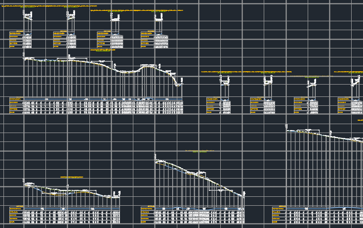
Views are created in a gridded arrangement.
Users specify a grid spacing x and y - the profile views are created starting from a grid position and span a multiple of grid positions. The next profile view will then be created at the next grid spacing.
A maximum width is also set. When profile views on a row exceed the maximum width, profile views will be created on the next row (defined by the y spacing of the grid) so that it doesn't overlap with the previous row.
Example output
An example of the outcomes of the command is shown below, with the grid spacing displayed:
Details
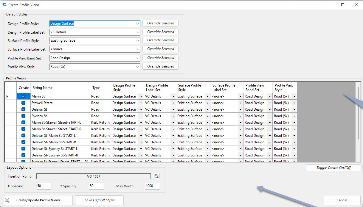
If a Civil 3D profile has been created for each String in the design, all the Civil 3D profiles will update elevations to match the Strings. After running this command, if a Civil 3D Profile can be created from a String the following form will display:
|
|
|
|
Default Styles |
These will be automatically assigned when a new String can be exported as a Civil 3D profile |
|
Design Profile Style |
Picklist of styles from the current drawing. Controls the display of the design profile. |
|
Override Selected |
Click to assign the selected Style to the highlighted profile views |
|
Design Profile Label Set |
Picklist of styles from the current drawing Controls the display of the profile view labels for the design profile. |
|
Override Selected |
Click to assign the selected Style to the highlighted profile views |
|
Surface Profile Style |
Picklist of styles from the current drawing. Controls the display of the sample surface profile. |
|
Override Selected |
Click to assign the selected Style to the highlighted profile views |
|
Surface Profile Label Set |
Picklist of styles from the current drawing. Controls the display of the profile view labels for the sampled surface profile. |
|
Override Selected |
Click to assign the selected Style to the highlighted profile views |
|
Profile View Band Set |
Picklist of styles from the current drawing. Sets the profile view band set to apply to created profile views. |
|
Override Selected |
Click to assign the selected Style to the highlighted profile views |
|
Profile View Style |
Picklist of styles from the current drawing. Sets the profile view styles to apply to created profile views. |
|
Override Selected |
Click to assign the selected Style to the highlighted profile views |
|
Profile Views |
Lists all Strings for output as profiles and profile views |
| [Selection column] | Can be used to select and hightlight rows. |
| Create | Tick on to create the Civil 3D profile/s in the drawing, as well as the profile view. |
|
Sring Name |
Displays the string name. Uneditable. |
|
Type |
Lists teh type of string. Uneditable. |
|
Design Profile Style |
Select the Design Profile Style to apply |
|
Design Profile Label Set |
Select the Design Profile Label Set to apply |
|
Surface Profile Style |
Select the existing ground (Surface) Profile Style to apply |
|
Surface Profile Label Set |
Select teh Surface Profile Label Set to apply |
|
Surface Profile Style |
Select the existing ground (Surface) Profile Style to apply |
|
Surface Profile Label Set |
Select teh Surface Profile Label Set to apply |
|
Profile View Band Set |
Select the Profile View Band Set to apply |
|
Profile View Style |
Select the Profile View Style to apply |
| Toggle Create On/Off | Toggles the Create cell on/off for the highlighted rows. |
|
Layout Options |
Sets a starting insert position for profile views as well as a grid spacing layout to output. |
| Insertion Point | Use the pick button to select a location in the drawing to insert profile views in the drawing. |
| X Spacing | Set a horizontal grid spacing. Profile views will be created at a grid line. |
|
Y Spacing |
Set a vertical grid spacing. Profile views will be created at a grid line. |
|
Max Width |
Type in the maximum width for the display of profile views in the drawing per row |
| Create/Update Profile Views |
Click to add profile views in the drawing for all Strings
with Create toggled on. If profile views are already created, the profiles will be udpated. |
|
Save Default Styles |
Save the styles to the Global Drawing Settings. |