Toolspace
Icon: |
 |
Introduction
From the Toolspace, users can view, create,
edit, delete and manage display of all Stringer data in the drawing
The Toolspace provides a centralised location
for all object data created with Stringer Topo.
The Toolspace displays as a traditional CAD
panel, able to be docked, anchored, auto-hidden and repositioned like
any other panel in the CAD platform.
AutoCAD/BricsCAD Platform
 |
Civil 3D Platform
|
Toolspace Tabs
Along the edge of the Toolspace panel are
the following tabs:
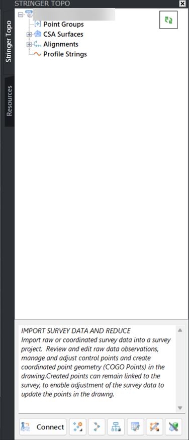
Data tab
The Data tab is organised in a tree structure
and complete with context menus and object icons:
Project Settings (right click on the
drawing name)
Object Collections (Object types that
contain Objects below it), logically grouped in creation order from
top to bottom. Object Collections include Point Groups, Surfaces,
Alignments and Profiles.
Stringer Objects. These
are individual objects in the drawing able to be edited or deleted
via right click.
Wherever shown, users can click on the + or
- symbol to expand or collapse a collection to see objects for that collection.
At the bottom of the Toolspace are quick access
commands related to overall import, creation, editing and output processes.
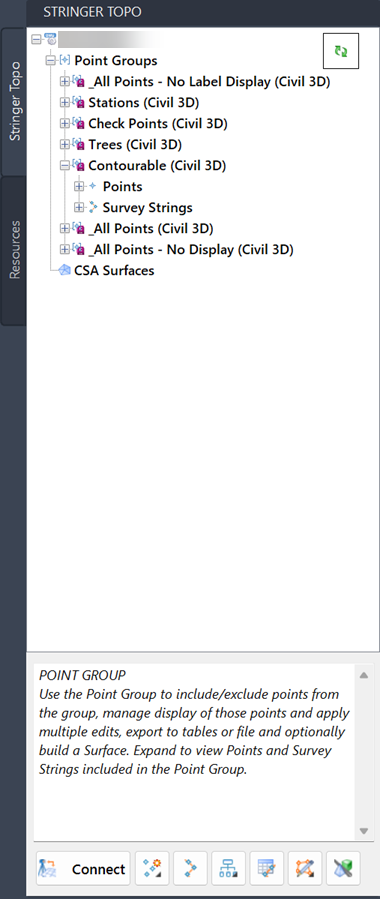
Point Groups
Point Groups create filtered lists of points,
from which Survey Strings can be created and points managed.
In Civil 3D, users can create a Link between
the Civil 3D points in a Point Group to enable editing, creation of survey
strings and output. Linked Point Groups are displayed in the
Point Groups object collection.
Alignments
Alignments provide the plan geometry for creating
long and cross section outputs, as well as creation of Cogo points along
an alignment. All alignments are listed in this Object collection,
including Civil 3D alignments (when operated in a Civil 3D environment).
Right click on any alignment to use it for
creating a String.
Alignments that are in use will display an
icon with a small green circled tick.
Object Collections
Object Collections are organised from top
to bottom in the Toolspace to match the design workflow. Objects
are shown under each group:
Point Groups
Point Groups provide contain filtered
collections of points.
Each Point Group contains Cogo
Points and Survey Strings
Point Groups can be used to create
surfaces including the points and survey strings contained in
the Point Group
Point Groups, Cogo Points and
Survey Strings can be managed here
In Civil 3D, Point Groups listed
here may be Linked to Point Groups in Civil 3D. In
this case, the linked point group provides functionality to manage
the Civil 3D point geometry and properties using Stringer
CSA Surfaces
Surfaces created by Stringer are
displayed here.
Surfaces can be created here by
the user.
Pasted surfaces and surface volumes
will be displayed here (these require both Surfaces to be Stringer
(CSA) Surfaces as opposed to Civil 3D surfaces
Surfaces created via satellite
data will be displayed here
A default surface named TotalModel
may be displayed here. This surface supports design
objects created using an associated application, Civil Site Design.
Civil 3D surfaces are not displayed
here. In Civil 3D, it is usual to Link to a Civil 3D
Point group and add breaklines from Survey Strings to a Civil
3D Surface.
Alignments
Alignments represent horizontal
geometry and may be used for many purposes, such as to describe
design elements, provide comparison to survey data..
Alignments can be selected for
creation of Profile Strings for creation of existing ground long
sections and cross sections, as well as stakeout.
The Alignments object collection
is not displayed in Civil 3D. Users may use the Civil
3D alignment, profile view and section view tools.
Profile Strings
Profile Strings use alignment
geometry and store vertical information extracted from a surface
Profile Strings can be used to
generate profile view and cross section outputs.
The Profile Strings object collection
is not displayed in Civil 3D. users may use the Civil
3D, profile view and section view tools.
Object Highlighting
Hover on an a Point or Survey String to highlight
that object in the drawing. For many objects, a double click
will act as a zoom to the object - right click Zoom is also available.
In the CAD platform, hover over an alignment
or profile string in the tooslpace to highlight it in the drawing
Running Commands from the Toolspace
To run commands from the toolspace, right
click on any Object Collection (eg: Alignment heading) or an individual
Design Object (eg: Alignment) to obtain a context menu of relevant commands:
Object
Collection Commands
 |
Object
Commands
 |
Point Groups - Managing Cogo Points, Survey
Strings and Surfaces
The Point Groups are central to the management
of Cogo Points, Survey Strings and Surfaces.
Both Points and Survey Strings are subsets
of Point Groups.
Expand a Point Group to see Cogo Points and
Survey Strings belonging to that group.
Initial Toolspace Display for new projects
Where the software has never been started
on a drawing, the user will be invited to 'Launch' Stringer Topo. This
will generate program settings for the drawing to support the software. A
data folder will be created to store data.
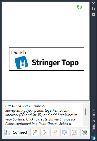
After clicking Launch Stringer Topo,
the Toolspace will display the object list.
Refreshing the Object List - Civil 3D
If it is desired to do a full update of the
point groups, points, survey lines, surfaces and plan labels, click on
the  Refresh button to update.
Civil 3D and Stringer Topo
It is usual to work with the Civil 3D Cogo
points and surfaces when importing survey data and producing survey surfaces
and survey strings.
COGO Points and Point Groups - Linking to
Civil 3D Point Groups
It is critical to create a Link to a Civil
3D Point Group to enable creation and editing of Civil 3D points using
Stringer, the creation of Survey Strings and the addition of breaklines
to Civil 3D surfaces.
In the Civil 3D platform, Importing points
using Stringer Connect will create Civil 3D Cogo Points and automatically
Link to Civil 3D Point Groups. If points are otherwise imported
into Civil 3D, users need to run the Civil 3D Points Link (Civil 3D Point
Group Link in the toolspace) command to enable Stringer to manage the
Civil 3D points and Civil 3D surface breaklines.
When Survey Strings are created, the breaklines
can be added to any Civil 3D surface (usually the point group and survey
strings are contained in the same surface), either as a Breakline File
(fastest) or as individual Breaklines (slowest - this adds a named Breakline
entry per Point Code/String combination)
Stringer (CSA) Surfaces vs Civil 3D Surfaces
Stringer does incldue a Surface (DTM) engine,
however most customers will opt to directly use the Civil 3D Surfaces.
Surfaces created by Stringer are known as
CSA Surfaces, and are often referred to a 'Quick Surfaces'. It
is common in associated applications, such as Civil Site Design, to create
dynamic 'quick surfaces' while designing, then to output them as Civil
3D surfaces for presentation and output.
Some commands in Stringer may be used to create
CSA Surfaces instead of Civil 3D Surfaces. CSA Surfaces will
be displayed under the CSA Surfaces object collection group in the Toolspace.
Details
After selecting the command, the Toolspace will display (CAD Platform
left and Civil 3D Platform right):
|
Launch |
If
this is a new project, click on this button to initialize the
Toolspace to display the object listing./td> |
Refresh (Update) |
If
Civil 3D points are added or removed from a linked Point Group,
use this button to update all Linked Civil 3D Point Groups.
In other platforms, this button will force a
full update of surfaces, including paste and volume surfaces,
as well as updating of the created profile strings (for when the
base surface changes).
This command also executes the Update
All command. |
Panel Tabs |
Tabs are displayed along the edge of the
Toolspace. |
Data tab |
Contains all Stringer Topo data, listed
in a tree view arranged by object type. |
 [Drawing Name]
 |
Right
click commands:
Drawing
Settings |
Manages
the overall behaviour of Stringer Topo.
Click to open the Active
Drawing Settings command. |
Toolspace
Settings |
Includes
functionality to manage the display of the Toolspace. Inputs
include:
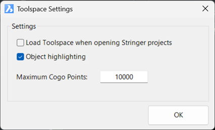
|
Load
Toolspace when opening Stringer Projects |
If
toggled on, when a drawing is opened it is scanned
for Stringer Topo data. If the drawing
contains Stringer Topo data, the toolspace will
open. |
Object
Highlighting |
Tick
on to enable object highlighting in the drawing
when hovering on an object. |
| Maximum
Cogo Points |
The
Toolspace redraw and display can slow when there
are a large number of objects listed. It
is highly recommended to limit the number of Cogo
Points displayed in the Toolspace to prevent unacceptable
lag. The additional points will not
be represented in the Toolspace. |
OK |
Apply
and exit. |
|
Project Storage |
Enables
saving of the Stringer Topo data inside the drawing (.dwg)
file and management of where the data is stored during
editing.
Click to open the Pack
Data Settings command. |
String
Defaults |
Sets
defaults for Point Code Settings, Survey String Settings
and Default Point Style for alpha and numeric coded COGO
points.
Click to open the String
Defaults form. |
Template
Editor |
Templates
(multiple offsets) can be added to any Survey String -
useful to represent standard sectional infrastructure
such as curbs. This will open the Template
Editor to enable creation, editing and management of Templates.
Click to start the Create/Edit
Templates command. |
Point
Code Set |
Sets
up Point Code Settings to establish layers and point styles
to apply based on COGO point descriptions.
Click to open the Point
Code Settings form. |
| Point
Styles |
Point
Styles set how COGO points are displayed as well as available
point properties
Click to open the Point
Styles form. |
| Point
Formats |
Establishes
the file format for importing/exporting points and controls
how COGO point descriptions are interpreted as Code, String
Number and other point properties
Click to open the Point
Formats form. |
Point Property Display
[Not available in Civil 3D] |
Allows select point display properties
to be hidden for all points in the drawing.
Click to open the Point
Property Display form. |
Survey
String Settings |
Establishes
how survey strings are connected based on COGO point descriptions.
Click to open the Survey
String Settings form. |
| Survey
String Parameters |
Set
parameters that may be applied to Point descriptions to
change the way survey linework is connected between points.
Click to open the Survey
String Parameters form. |
| Replace
Code Settings |
Applies
bulk changes to point codes. This establishes
the code pairs.
Click to open the Replace
Code Settings form. |
| Group
Table Styles |
Table
settings for output of Cogo Point and Survey String tables
for selected Point Groups.
Click to open the Point
Group Table Settings command. |
Image
from Satellite |
Import
a background image from the web and add as a .png XREF.
Click to open the Image
from Satellite form. |
|
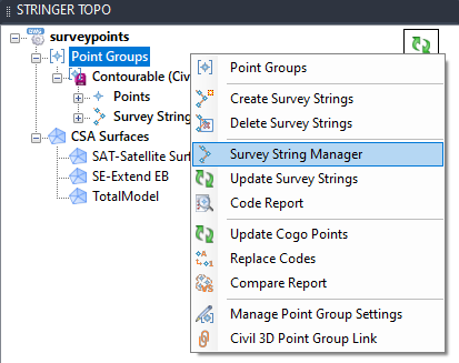
 Point Groups Collection
 |
Right
click commands:
Point
Groups |
Point
groups provide filtered lists of points that can be used
to manage display and create surfaces
Click to open the Point
Groups form. |
Create
Survey Strings |
Survey
Strings connect like points in a Point Group (points that
have the same description and, optionally, String number)
together with 2D and/or 3D polylines, and can be applied
as breaklines to a surface.
Click to Create
Survey Strings.
If already created, this command allows editing of the
survey string group behaviour. |
| Delete
Survey Strings |
Deletes
all Survey Strings added to a Point Group.
Click to Delete
Survey Strings. |
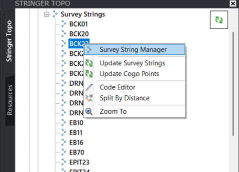
| Survey
String Manager |
Opens
a dedicated interface to select points and survey strings
for editing.
Click to open the Survey
String Manager form. |
| Update
Survey Strings |
Forces
an update to survey strings. Click to Update
Survey Strings. |
| Code
Report |
Reviews
the Codes (descriptions) of Cogo points in the drawing
and compares to the Point Code Set and Survey String Set
table.
Click to open the Code
Report form. |
| Update
Cogo Points |
Forces
an update to cogo points. Click to Update
Cogo Points. |
| Replace
Codes |
Enables
bulk replacement of Point Codes in the drawing. Click
to start the Replace
Codes command. |
| Compare
Report |
Generate
comparison reports between points, surfaces, alignments
and polylines.
Click to run the Compare
Report command. |
|
Point Inquiry |
Starts the Point
Inquiry command. Obtain information comparing two
points. |
Manage
Point Group Settings
[Civil 3D only] |
Manages
how breaklines are added to the surface from Stringer.
Click to open the Manage
Point Group Settings form. |
Civil
3D Point Group Link
[Civil 3D only] |
Link
to Civil 3D point groups to enable management of the Civil
3D point geometry.
Click to open the Civil
3D Point Group Link form. |
|
Point Group
 Point Group [Civil 3D Linked]
 |
Right
click commands:
Point
List |
Click
to open the Point
List of all points in the Point Group. |
| Apply
Styles from Code Set |
Click
Apply
Styles from Code Set to change the applied Point Style
for every point in the point group based on the point
descriptions, to match with the Point Code Set selected. This
is useful when the Point Code is changed and it is desired
to change the display of the point and/or the stored point
properties.
Note: In Civil 3D, this command will not alter the point
display - this is managed by Civil 3D Point Styles. |
|
 Points
Collection Points
Collection |
Right
click commands:
Code
Editor |
Click
to open the Point
Code Editor.
Enables editing of multiple point codes, string numbers
and parameters. |
| Update
Cogo Points |
Forces
an update to cogo points. Click to Update
Cogo Points. |
|
Points |
Right
click commands:
Edit
Cogo Point |
Edit
the currently selected Cogo Point. Click Edit Cogo Point. |
| Zoom
To |
Click
to zoom to the Cogo Point in the drawing. |
|
Survey
Strings Collection |
Right
click commands:
Create
Survey Strings |
Survey
Strings connect like points in a Point Group (points that
have the same description and, optionally, String number)
together with 2D and/or 3D polylines, and can be applied
as breaklines to a surface.
Click to Create
Survey Strings.
If already created, this command allows editing of the
survey string group behaviour. |
| Survey
String Manager |
Opens
a dedicated interface to select points and survey strings
for editing.
Click to open the Survey
String Manager form. |
| Update
Survey Strings |
Forces
an update to survey strings. Click to Update
Survey Strings. |
| Update
Cogo Points |
Forces
an update to cogo points. Click to Update
Cogo Points. |
| Code
Editor |
Click
to open the Point
Code Editor.
Enables editing of multiple point codes, string numbers
and parameters. |
|
Survey
Strings |
Right
click commands:
Survey
String Manager |
Opens
a dedicated interface to select points and survey strings
for editing.
Click to open the Survey
String Manager form. |
| Update
Survey Strings |
Forces
an update to survey strings. Click to Update
Survey Strings. |
| Update
Cogo Points |
Forces
an update to cogo points. Click to Update
Cogo Points. |
| Code
Editor |
Click
to open the Point
Code Editor.
Enables editing of multiple point codes, string numbers
and parameters. |
| Split
by Distance |
Splits
Survey Strings for string segments longer than a user
input value. Click to Split
by Distance. |
| Zoom
To |
Click
to zoom to the start of the Survey String in the drawing. |
|
 CSA Surfaces Collection
 |
Right
click commands:
Surface
Manager |
Click
to open the Surface
Manager form.
The Surface Manager is used to manage the inputs to a CSA
Surface as well as the display in the drawing: contours,
triangles, slopes, slope arrows, elevations and directions. |
Create/Update from LAS |
Click
to open the
Surface from LAS form.
The Surface from LAS command imports LAS files directly to
create surfaces. |
Toggle
Display |
Click
to open the Toggle
Display form.
The Toggle Display form provides a single interface for
managing the display of contours and triangles for multiple
CSA Surfaces |
Volumes |
Undertake
Surface-to-Surface volume comparisons for CSA Surfaces. Click
to start the Surface
Volume command. |
Paste
Surfaces |
CSA
Surfaces can be pasted together. Click to start
the Paste Surfaces
command. |
Update
Paste Surfaces |
This
command rebuilds/updates all pasted surface objects. Click
to Update Paste
Surfaces. |
Update
Water Drops |
If
the Water Drop command has been run, this command redraws
the water drop paths - useful if the surface has been
edited. |
Model
Viewer |
Click
to open Model
Viewer. |
|
CSA
Surface |
Right
click commands:
Surface
Manager |
Click
to open the Surface
Manager form.
The Surface Manager is used to manage the inputs to a CSD
Surface as well as the display in the drawing: contours,
triangles, slopes, slope arrows, elevations and directions. |
Toggle
Display
[Civil 3D only] |
Click
to open the Toggle
Display form.
The Toggle Display form provides a single interface for
managing the display of contours and triangles for multiple
Surfaces |
Toggle
On/Off Contours |
Toggles
on/off the display of the contours for the selected Surface |
| Toggle
On/Off Triangles |
Toggles
on/off the display of the triangles for the selected Surface |
| Add
Water Drop |
Starts
the Water Drop
command. |
| Delete
Surface |
Deletes
the selected Surface |
|
 Alignments Collection
[Not Civil 3D] |
Right
click commands:
Create Alignment |
Click to start the
Create Alignment command. |
Best Fit Alignment |
Opens the
Best Fit Alignment form to create an alignment best fit
using COGO Points or a polyline. |
|
/  Alignment Alignment
[Not
Civil 3D] |
Icon
display changes if the alignment is being referenced by a String
Right click commands:
Create
Profile |
Create
a Profile String from the alignment.
Click to start the Profile
String command. |
Edit
Alignment |
Click
to open the Edit
Alignment form for the selected alignment.
[Not available for Civil 3D alignments] |
Grid
Editor |
Opens
the grid editor to edit alignment geometry.
Click to open the Alignment
Grid Editor form. |
Delete
Alignment |
Click
to delete the current alignment. A message
will display to confirm deletion.
If the alignment is being used as a String, the alignment
will not be deleted and a message will display. |
|
 Profile Strings Collection
[Not Civil 3D] |
Right
click commands:
| Update
String Elevations |
Resamples
all created Profile Strings against the sampled surface
set in each Profile String. Elevations of the
Profile Strings are updated to match the elevations of
the Sampled Surface set in each Profile String. |
|
Profile String
[Not
Civil 3D] |
Right
click commands:
|
Hover
Text Panel |
Displays
information text as each Object Collection or Object is hovered
over |
|
|
Stringer
Connect |
Import
and reduce survey data.
Click to open the Stringer
Connect form. |
Point
Tools |
List
of Cogo Point commands.
Import
Cogo Point File |
Use
a file to import coordinated point geometry (Cogo) into
the drawing. Click Import
Cogo Points. |
Import
Cogo Point File (by alignment) |
Use
a file to import station/offset input files (Cogo) into
the drawing, referencing an alignment. Click
Import Points by Alignment
command |
Import XML |
Import Trimble JXL |
Import a
Trimble XML file to create coordinated points and/or add
Data Tables and attribute data Fields to COGO Points |
|
Import Leica XML |
Import a Leica
XML file to create coordinated points and/or add Data Tables
and attribute data Fields to COGO Points |
|
Create
Cogo Points |
Create Cogo Points
in the drawing. |
| Create
by Reference |
Create
points that have a dynamic reference (horizontal and/or
vertical) to other objects. Click Create
by Reference. |
| Create
by Polyline |
Creates
points along a polyline. Click Create
by Polyline. |
| Create
on Grid |
Creates
points in a gridded pattern in the drawing. Click
Create on Grid. |
| Draw
Cadastral Lines |
Create
linework and points with bearing and distance input. Click
to open the Draw
Cadastral Lines form. |
| Convert
Objects to Cogo |
Convert
2D and 3D objects in the drawing (Text, Mtext, Points
and Blocks) into Cogo points. Click Convert
Objects to Cogo. |
Multi
Symbols |
Creates
multiple blocks over a single point pickup, with scaling extracted
from the point description.
Click to add Multi Symbols
to the drawing. |
|
Create
Survey Strings |
Survey
Strings connect like points in a Point Group (points that have
the same description and, optionally, String number) together
with 2D and/or 3D polylines, and can be applied as breaklines
to a surface.
Click to Create
Survey Strings. |
Project Database Tools |
List of
commands supporting the attachment of Data Tables (attributes) to COGO
Points and Survey Strings.
Setup Project Database |
Establishes a
Project Database for storing Data Tables and attribute Field
data on COGO Points and survey Strings in your project/s |
|
Create Object Tables |
Starts the
Create
Object Tables comand. Attach Data Tables to objects in
the drawing. |
|
Sync to Survey Strings |
Starts the
Sync to Survey Strings command.
Transfers COGO Point Data
table information onto associated Strings. |
|
Sync COGO Point Properties |
Starts the
Sync to COGO Points command.
Creates Point Properties for
each data table field on each COGO Point. |
|
Sync to Property Sets (Civil 3D Only) |
Sync to Property Sets |
Transfers the Data Table field information to Property Sets |
|
Sync From Property Sets |
Transfers the Property Set information to the Data Table Fields. |
|
|
Editors |
Schema Editor |
Starts the Schema
Editor command. The Schema Editor manages the Data
Tables and Fields included in a Schema. |
|
Field Validator Editor |
Starts the
Field Validator Editor command. Field Validators set
allowing field inputs for data fields. |
|
COGO Point Table Map |
Starts the
COGO
Point Table Map command.
Automates the assignment of Data
Tables to COGO Points based on the point Code. |
|
Survey String Table Mape |
Starts the
Survey String Table Map command.
Automates the assignment
of Data Tables to Survey Strings based on the point Code of the
string. |
|
|
Table Viewer |
Opens the Table Viewer
to review all data attached to objects. |
|
Edit Tables |
COGO Point Table |
Starts the
COGO
Point Table command to edit data attached to each COGO Point |
|
Survey String Table |
Starts the
Survey String Table command to edit data attached to each
Survey String. |
|
|
Export Database |
|
|
| Create
Point Group Table |
Generate
point and survey string tables. An example would be
a legend table for created points.
Click to start the Create
Group Table command. |
Cadastral Tools |
List of
cadastral tools
Traverse Editor |
Open the
Traverse Editor. |
Transform
Points |
Apply
Helmert or Affine transformations, as well as Datum adjustments,
to points.
Click to start the Transform
Points command. |
|
Model
Viewer |
Click
to start the Model
Viewer command. |
Resources tab |
The Resources tab includes help resources
for new and existing users |