Cadastral Lines
Icon: |
|
Introduction
This command provides functionality to keyboard enter in traverse lines and side shots, creating points starting from a base point.
Creating a Traverse and or Sideshots requires creation of a Cadastral Lines Group - this Group lists all the added traverse/sideshot points and provides direct editing of the values to udpate the points and polylines in the drawing.
Angles are input in this format: 95.3045 would be 90° 30' 45".
Lengths are typed as a real positive number and can be created using different measurement units: metres (unadjusted in metric settings), feet (unadjusted in survey feet or feet drawings), Chains, Links, Inches
Elevations can be set by the user or an Elevation Reference can be established between the Base Point and the created Point. Elevation changes to the Base Point would then update the elevations of the referenced Points.
A COGO Point is required to start - the user can select one from teh picklist, pick from the drawing or use the Create button to create a new Base Point.
This form is modeless, so users can zoom/pan to navigate in the drawing as well as do other commands. Edits made to the created points in the Group table will immediately update the traverse/sideshots in the drawing.
There is an Auto Zoom function to zoom to the next created segment or selected segment, defaulting on whe the form is opened.
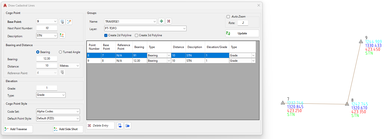
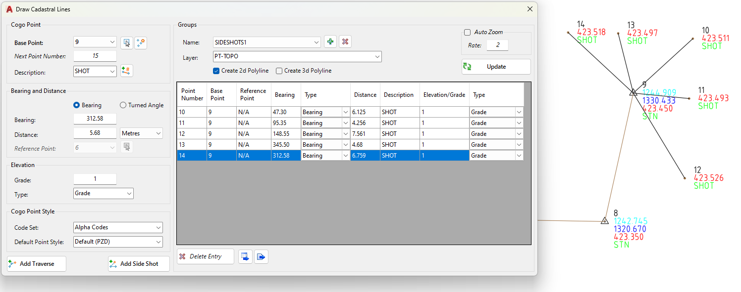
It is recommended to create Traverse Groups separate to Side Shot Groups. If a Side Shot is added after a Traverse in the same Group, the linework of that traverse will be removed.
Examples of a Traverse line group and a Sideshot line group:
Details
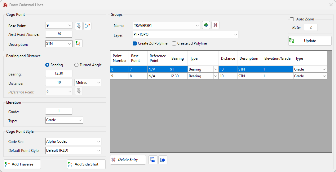
Upon selecting the command the following form is displayed:
|
|
|
|
COGO Point |
Set up the point number, base point and point description |
|
Base Point picklist |
Pick any created COGO point in the drawing to use as a Base Point |
|
Select from drawing |
Click to then pick a COGO poitn from the drawing |
|
Create New Point |
Opens the Create Points form for creation of points to use as a Base Point |
|
Next Point Number |
Controls the next created Point Number |
|
Description |
Type in or pick a Description for the created point/s. The picklist of points is inherited from the selected Code Set |
|
Append unique String Number |
Appends a unique String number to the point/s that will be created. This supports creation of Survey Strings between the points. Note: this command will only apply if Create Survey Strings has been run previously in the drawing. |
|
Bearing and Distance |
This is the core input for setting the horizontal position of the created point/s |
|
Bearing radiobutton |
Select to create Points based on Azimuth angles (0° north, rotating to 360°) |
|
Turned Angle radiobutton |
Select to create Points based on a turned angle measured relative to a line formed between the Base Point and the selected Reference Point |
|
Bearing |
Type in a bearing. Format: 95.3045 is input as 90° 30' 45". |
|
Distance |
Type in a positive number for distance. |
|
Unit picklist |
Select the units for drawing the line |
|
Reference Point picklist |
Enabled if Turned Angle is selected. Pick a COGO Point to set the reference direction to the Base Point |
|
Select from drawing |
Select the turned angle reference point from the drawing |
|
Elevation |
Establish the elevation as a fixed elevation value or by reference to the Base Point |
|
Grade/Elevation |
Type in a percentage Grade or Elevation |
|
Type |
Select how the elevation is assigned: - Grade: type in a percentage grade to calculate the elevation from the Base Point - Fixed Elevation: type in the elevation - Elevation Difference: type in an elevation difference from the Base Point |
|
COGO Point Style |
|
|
Code Set |
Select the Code Set to use for assigning the Point Style to created points. |
|
Default Point Style |
Default Point Style. Optional default Point Style to apply if the point is not assigned from the Code Set |
|
Add Traverse |
Click to create a new Point and draw a polyline from the Base Point to this new Point. When clicked, the Base Point will be adjusted to equal the newly created Point. The Next Point Number field will be incremented |
|
Add Side Shot |
Click to create a new Point and draw a polyline from the Base Point to this new Point When clicked, the Base Point will not change. The Next Point Number field will be incremented. |
|
Groups |
|
|
Name (Group picklist) |
Picklist of all created Groups. Select a Group to display points created for that Group |
|
Add New |
Create a new Group |
|
Delete Current |
Delete the selected Group. This will not delete any points or linework created for the Group |
|
Layer |
Select the layer to draw polyline/s on between the Base Point and new Point |
|
Create 2D Polyline tickbox |
Tick on to draw 2D polyline/s between points |
|
Create 3D Polyline tickbox |
Tick on to draw 3D polyline/s between points |
|
Auto Zoom |
Auto zoom to points as they are created. |
|
Auto Zoom tickbox |
Tick on to enable auto zoom |
|
Rate |
Sets the zoom scale. Smaller number is a closer zoom in. Larger number is a zoom out. |
|
Update |
Update all COGO points and drawn linework |
|
[Group Table] |
Editable table describing the point data, bearing, distance and elevation |
|
Point Number |
Point Number. Not intended to be edited |
|
Base Point |
Base Point. Not intended to be edited |
|
Refrence Point |
Reference Point. Not intended to be edited |
|
Bearing |
Type in the bearing |
|
Type |
Type of angle measurement. Not intended to be edited |
|
Distance |
Type in the distance |
|
Description |
Type in the description |
|
Elevation/Grade |
Type in the elevation/grade input |
|
Type |
Set the Type of elevation calculation (Grade, Elevation difference, Fixed elevation) |
|
Delete Entry |
Delete the selected entry from the Group list. The point and linework will not be deleted from the drawing |
|
Export to Table |
Export the Group table data as a Table object in the drawing |
|
Export to File |
Export the Group table data to a .csv file. The file will open using the default application for this extension |