Multi Symbols
Icon: |
|
Introduction
This command creates multiple, user scaled blocks, inserted at the location of COGO Points in the drawing. The scaling of the blocks is defined by the user in the point description. This is especially useful for when different symbology, with different scales, needs to be presented in the drawing.
The most common use of this command would be for trees, where the user decides to pick up a single shot for the tree but needs to describe the trunk diameter/radius and canopy diameter/radius separately. This command works independenly of the individual point Code, by looking at the format of the point description.
The key to operation of the Multi Symbol command is:
-
Deciding on the format of the point code pickup and which parts of the description describe scaled blocks to include (eg: TR 0.5 8 12 could describe a tree with a trunk of 0.5m (requiring a block describing a trunk), a canopy of 8m (requiring a block describing a tree canopy), and a height of 12m (requiring a 3D block describing the canopy width of 8m and height of 12m)). These 'Scale Parameters' are separated by Spaces.
-
Creating unit-sized (1 unit) blocks and placing them in the Settings folder (by default, C:\ProgramData\CSS\CSD\Common\common-10\Point Styles) for reference by the Multi Symbols command
-
Creating and applying a Point Format that describes the formatting of the point description for each scaled block that is to be inserted.
-
Creating a Point Group with the points that should have multiple scaled blocks assigned
-
Starting this command and setting the Point Group, Point Format, blocks and scale parameters to apply to points in the drawing
Setup and Behaviour
Point Description
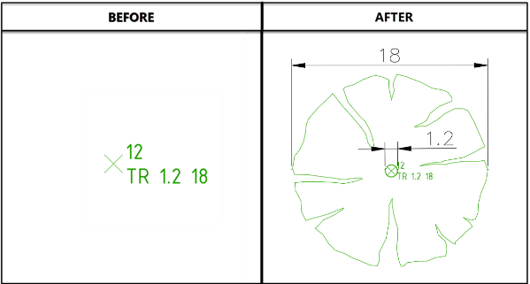
In a point description for a Tree that has a different scaled trunk to canopy, the point description may be as follows:
TR 1.2 18
In this description, the format of the point is:
[Point Number] [Trunk Diameter] [Tree Canopy Diameter]
Or, described another way:
'Code' 'Scale Parameter 1' ' Scale Parameter 2'
The Multi Symbols command requires a Point Format to be created to read the Point Description and assign custom Point Properties to each of the Scale Parameters. An example of a created Point Format for this purpose is shown below:
Point Format Setup
A Point Format is then created to interpret the point description and assign a Point Property for each 'Scale Parameter':
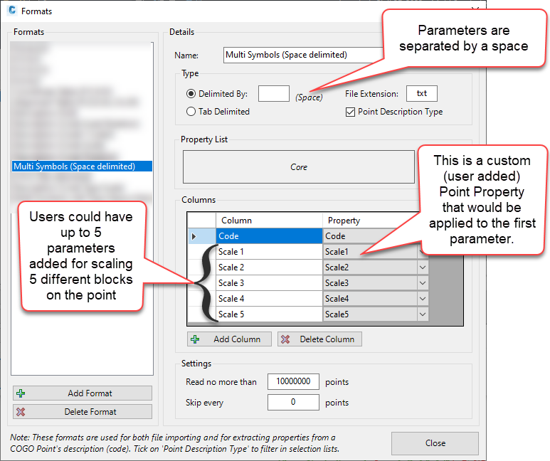
In the above, up to 5 Scale Parameters could be added after the Code and support 5 blocks, scaled for each of the 5 Scale Parameters typed in after the Code. In the raw point description, each input after the Code, separated by a space, will be interpreted as a Scale Parameter and used to scale a block inserted at the point location.
Special Note: The Multi Stakeout form will programmatically ADD these Point Properties to COGO Points when blocks are added. The points should originally not have these Point Properties assigned.
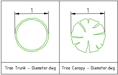
Resource Blocks
Unit sized (1 unit representing the the width/diameter or, in the case of a tree, the radius) drawing files are created for each parameter. These will be scaled based on the parameter value found on the point.
Multi Symbols Command - Applying Blocks, Point Format and Point Properties
Unlike most other functions in the software, the Multi Symbols command is intended to add (create) Point Properties for each COGO Point, then to use the value in each Point Property to scale each block on the point
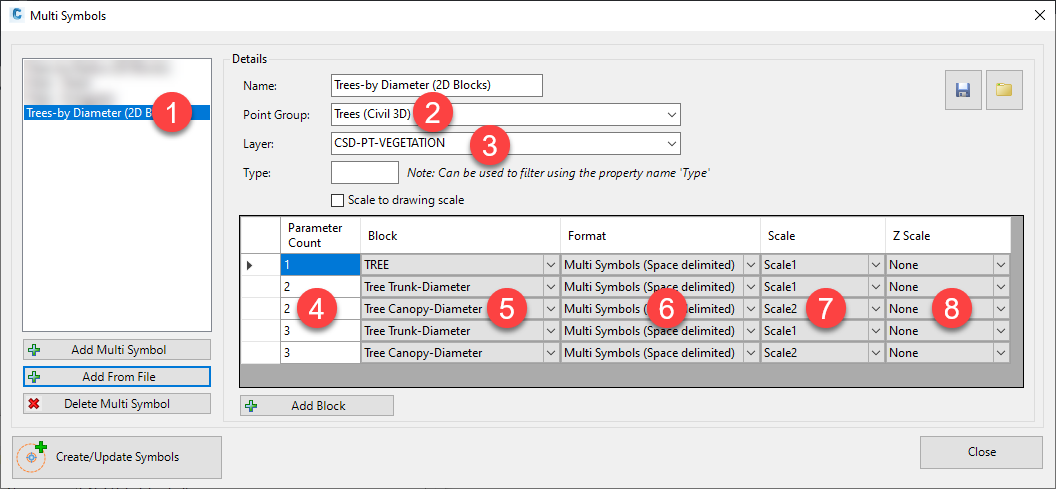
In the Multi Symbols command, the process is:
-
Create a Multi Symbol Group. Most efficient method is to use Add From File and create from a saved file, then edit.
-
Select the point group for COGO points to apply symbols to
-
Pick a layer to create the blocks on
-
Set the number of Scale Parameters that the block has (eg: TR 5 has one Parameter after the Code, TR 1 6 has 2 Parameters after the Code, TR 1 6 20 has 3 Parameters after the Code)
-
Pick the block to add
-
Pick the Point Format (describing how the point description is formatted into Point Properties
-
Pick the Point Property from the Point Format, to use to scale the block in the x,y plane
-
(Optional) Pick the Point Property from the Point Format, to use to scale a 3D block in the z plane
Clicking Create/Update Symbols will then add the blocks to the point/s that have the corresponding point description format.
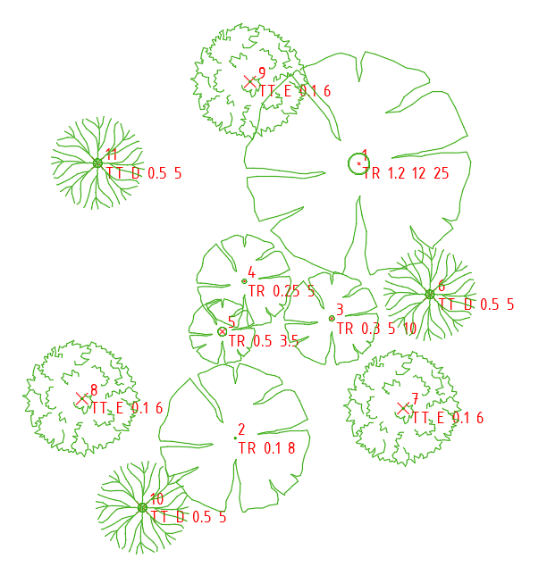
Use Point Type to manage display
If Points contain a Point Property called Type, then users can fillter the points to have blocks assigned by checking the value in the Type property. Only points with a matching Type property will have the block/s assigned.
Below is an example of multiple blocks assigned, with different blocks assigned based on the Point Property 'Type' of the points.
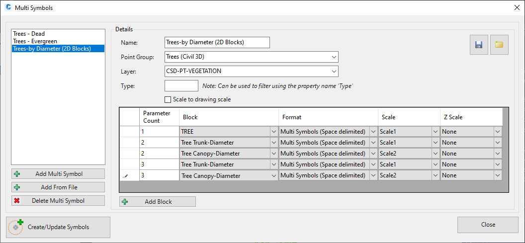
Details
Upon selecting the command the following form is displayed:
|
|
|
|
Multi Symbol Table |
This lists all Multi Symbol tables and includes options to add and delete tables |
|
[List of Multi Symbols] |
List of created Multi Symbol tables. Click on a Multi Symbol in the list to set it for editing on the RHS of the form |
|
Add Multi Symbol |
Click to add a new Multi Symbol entry. A default Name will be assigned and this will be set on the RHS of the form for editing |
|
Add From File |
Click to open a navigation window to select a previously saved Multi Symbol table. This will add an entry and pre-polulate the RHS of the form. |
|
Delete Multi Symbol |
Deletes the highlighted Multi Symbol entry from the list. |
|
Details |
The Right Hand Side of the form provides functionality to set up the multiply scaled blocks to apply |
| Name | Type in a name for the Multi Symbol |
| Save | Save all the Multi Symbol contents to file for re-use with the Add From File button |
| Load Contents | Loads the contents of a saved Multi Symbol and replaces the contents of the current Multi Symbol inputs |
| Point Group | Select the Point Group containing the points requiring multi symbols |
| Layer | Pick a layer to draw each block on |
| Type | Optional. If COGO Points contain a Point Property called 'Type', then the Type input can be used to filter which Points have the block/s added |
| Scale to drawing scale | Tick on to have the blocks rescale based on the Model view Scale. If unticked the blocks will display at 1:1 scale in the drawing |
|
[List of Controls] |
|
|
Parameter Count |
Type in how many parameters are included (measured after the Code) in the point description. Allows for different block configurations based on how many sizing parameters are included in the point description. |
|
Block |
Picklist of blocks to add to the point/s |
|
Format |
Pick the Point Format to apply. This is used to assess the point description contents and assign Point Properties to each parameter found in the point description |
|
Scale |
Pick the Scale Parameter from the selected Point Format. The corresponding value in the point description will be assigned to this Point Parameter and then used to scale the selected block in the x,y direction |
|
Z Scale |
Pick the Scale Parameter from the selected Point Format. The corresponding value in the point description will be assigned to this Point Parameter and then used to scale the selected block in the z direction (note: the Scale field also must be set for the x,y scale of the 3D block selected) |
|
Add Block |
Adds another entry in the list for assigning another block to the point/s |
|
Create/Update Symbols |
Adds blocks to points in the drawing. |
|
Close |
Close the form |
.