Subgrade Model Manager
|
Icon: |
|
| Ribbon: | Roads Tab > Modeling Panel > Auto Model dropdown > Subgrade Model Manager |
Introduction
This command provides functionality to create subgrade surface models for any design (Auto Model or Model Builder model).
Users can select particular subgrade layers to include or omit in the creation of the subgrade model. Additionally, users can default the model creation to include only the Datum layer, to build a datum surface.
The Subgrade Model created can be included as a Surface in the drawing, exported as 3D polylines and used to create COGO Points.
The Subgrade Model Manager provides a graphical edting environment displaying the cross sections with each pavement layer (known as a region), the included/excluded section breaklines and the linear Code breaklines. As well, stations, the design surface and existing surface can be toggled on/off for display.
Users can graphically select and edit:
-
Any linear feature (defined by the corners of each subgrade layer extracted as linear breaklines along the string alignment) and choose to Omit or Include as a Linear Breakline. This will remove/add breaklines to the Subgrade Surface and also be included in a polyline export to the drawing or for point stakeout.
Users can use this linear feature to project a new Linear Breakline to match the surface (sampled or design) - this is knows as a 'Resolve to Surface' linear breakline
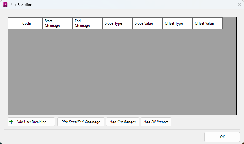
Users can add additional user breaklines offset vertically and horizontally from this Linear Breakline - this is known as a User Breakline -
Any section (defined as the top/bottom of each layer, drawn perpendicular to the string alignment) and choose to Omit or Include the section as a breakline. This will remove/add breaklines to the Subgrade Surface.
A Section can be used to Split the Linear Breakline, for editing over a station range
Both the Linear Breaklines and section lines display differently based on whether they are included or excluded from the model.
A 'Resolve to Surface' and 'User Breakline' can also be displayed differently in the model to distinguish them from other included/excluded linear or sectional breaklines.
When a Linear Breakline or section line is selected it will display bold (and optionally in a different color) in the viewer. A properties box will also display on the LHS to enable editing of the selected object. This is a dynamic properties window, displaying inputs relevant to the item selected.
Examples of display when sections and feature lines are selected:
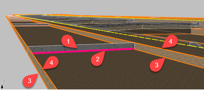
Section Line
 |
Code Feature Line
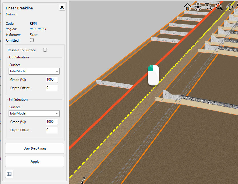 |
Subgrade Layer Anatomy
The Subgrade Model Manager displays multiple aspects of the subgrade layers, some of which are used to create a Subgrade Model surface.
Below is a screen shot of a single subgrade pavement layer for a path, with the subgrade surface displayed.
The key display elements for creating a subgrade are as follows:
-
Subgrade Regions: these display the cross section material layers at each sampled section on the String. The layer is displayed if the Code pair exists, as described in the Template. Optionally users can turn the Region subgrade layer display on/off (both for subgrade layers that are included or not included in the subgrade model output)
-
Sectional Breaklines: these are used in the creation of a Subgrade Model. Users can select any numbered Layer (described by a pair of Codes) and set whether to Omit (or Include) the bottom - when included this will add a Sectional Breakline for the subgrade layer at the bottom of the layer
-
Code Feature Line (bottom): the feature line for the bottom of any subgrade layer can be included or excluded form the model. For each numbered layer, users can choose to Omit (or include) the code Linear Breakline for the bottom of the layer
-
Code Feature Line (top): the feature line for the top of any subgrade layer can be included or excluded from the model. For each numbered layer, users can choose to Omit (or Include) the code Linear Breakline for the top of the layer
Curb type subgrades are also defined by a Code Pair - in this case the two codes would describe the front (lip) and back of the curb. When those two codes are present the software will provide access to the layers and subgrade details as they are defined in the Template.
For some subgrade layers, such as for Curbs, it may be desired to include a batter to the surface to describe a vertical/graded cut in the surface.
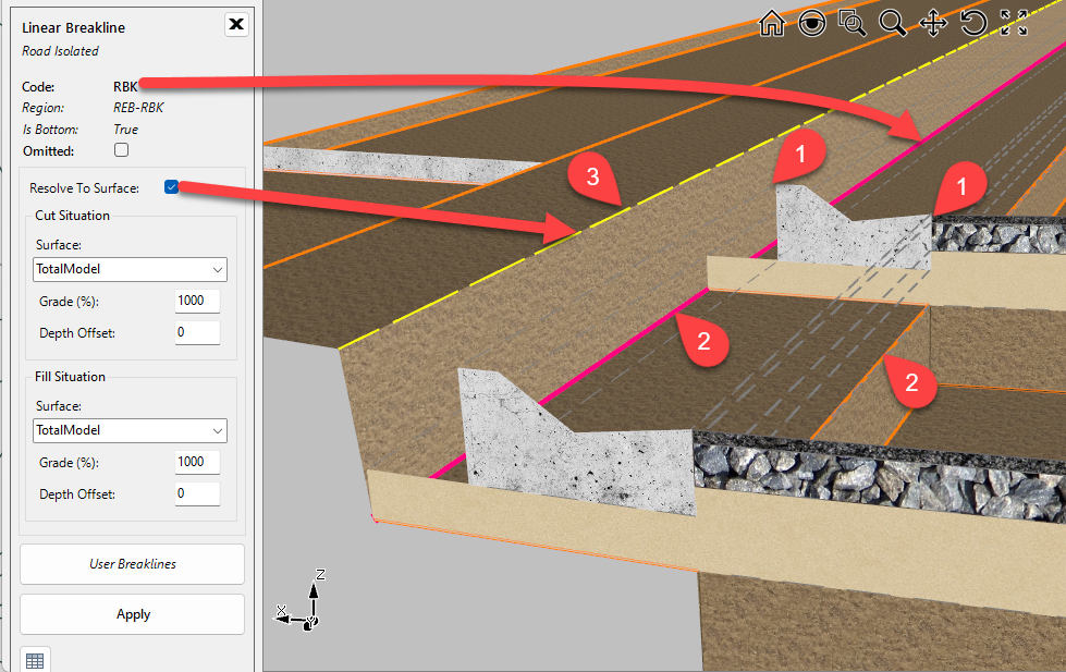
The key display elements for creating a subgrade with a batter (Resolve to Surface) is as follows:
-
Code Pair: defined by the top front and top back of the curb
-
Code Linear Breaklines (bottom): for a Curb type subgrade the bottom outer code may be an offset horizontally and vertically from the top of curb position.
-
The inner Code Linear Breakline (closest to the centreline) or outer Code feature line (furthest from the centreline) can have a batter (Resolve to Surface) applied. This wil add another feature line by projecting from the selected Code feature line to the surface (design or sampled) at a defined slope. These breaklines can be represented differently on screen.
Note: Where no layer has been set for a section of the template, no Subgrade Breaklines or Code Feature Lines will be included in the model. Adding a zero depth layer will trigger options to include the section breakline and code feature line/s.
Subgrade Linear Breaklines and Surface Models
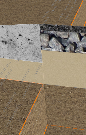
In order to support the creation of a surface from the subgrade layers, where there may be elevation changes occuring at a Code, the software extracts Code linear features for each subgrade layer and between each code pair, with a small separate (0.005) to facilitate surface triangulation.
At each Code location, there may be two subgrade layer feature lines displayed. One for the section left of the Code and one for the seciton right of the Code. It may be required to select both left/right feature strings for changing the omit status at each subgrade layer. Example below showing the Code for the lip of curb. There is a code feature line for each subgrade label left and right of the Code location to support the layer depths being different left/right of the Code.
Interface
The Subgrade Model Manager form is made up of the following components:
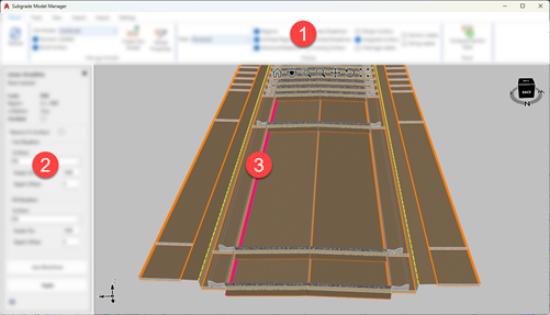
| 1 | Ribbon.
Create and manage subgrade models. Establish settings and styles, turn display on/off, import and export |
| 2 | Dynamic Properties panel.
Displays when an object is selected in the graphical window. Contents and options depends on the objects selected by the users |
| 3 | Graphical enviroment.
This is aninteractive display of the subgrade model breaklines (feature code breaklines and sectional breaklines), subgrade surface and other sectional data. Click on a Linear Breakline or Section Breakline to include, omit or edit the feature. |
Navigation
There are navigation tools at the top of the graphical display. When selected, that single nativigation mode will apply (except for the far right icon, which applies a Zoom Extents).
When no particular navigation mode is selected (highlighted), navigation is controlled as follows:
-
Orbit (hold down the middle mouse button)
-
Zoom (roll the middle mouse button)
-
Dymamic Zoom (Shift+middle mouse button)
-
Pan (Ctrl+middle mouse button)
-
Select (left click mouse button)
-
Edit menu (right click mouse button)
Subgrade Model Creation vs Editing
At the time of creation, users are prompted to select a Subgrade Section Style. This Style establishes which Code/s and which pavement (subgrade) layer/s to include or omit from the model. The Style also controls which Code/s need a 'Resolve to Surface' to be applied.
To simplify the setup, some default Subgrade Section Styles have been included with the initial install, aimed at creating a valid subgrade model automatically for most design situations.
When no particular navigation mode is selected (highlighted), navigation is controlled as follows:
-
Orbit (hold down the middle mouse button)
-
Zoom (roll the middle mouse button)
-
Dymamic Zoom (Shift+middle mouse button)
-
Pan (Ctrl+middle mouse button)
-
Select (left click mouse button)
-
Edit menu (right click mouse button)
Video Resources
These videos, hosted on Youtube, provide an overview of the software fucntionality for Subgrade modeling, including details around using Subgrade Model Manager: https://www.youtube.com/watch?v=BUV7Ifne5UU&list=PLa40O20aqztMssAKlSwFAF1nbcOb8WlGi&index=2
Details
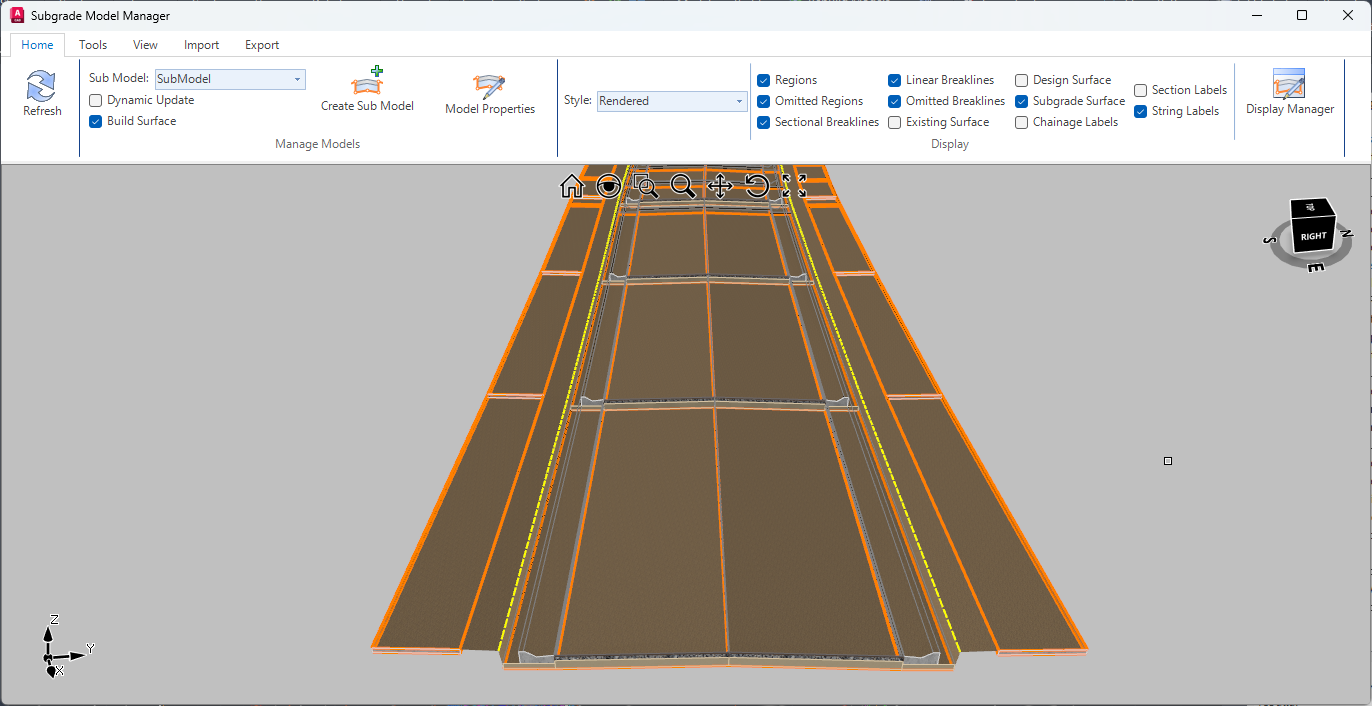
Upon selecting the command the following form is displayed (if no model is created, the screen will display only a background):
|
|
|||||||||||||||||||||||||||||||||||||||||||||||||||||||||||||||||||||||||||||||||||||||||||||||||||||||||||||||||||||||||||||||||||||||
|
RIBBON TABS
|
|
||||||||||||||||||||||||||||||||||||||||||||||||||||||||||||||||||||||||||||||||||||||||||||||||||||||||||||||||||||||||||||||||||||||
|
Home Tab |
Includes core controls for managing the display and general operations
|
||||||||||||||||||||||||||||||||||||||||||||||||||||||||||||||||||||||||||||||||||||||||||||||||||||||||||||||||||||||||||||||||||||||
|
|
If 'Dynamic Update' is unticked, click this button to update the subgrade model following a change to the design model | ||||||||||||||||||||||||||||||||||||||||||||||||||||||||||||||||||||||||||||||||||||||||||||||||||||||||||||||||||||||||||||||||||||||
|
Manage Models Panel |
|
||||||||||||||||||||||||||||||||||||||||||||||||||||||||||||||||||||||||||||||||||||||||||||||||||||||||||||||||||||||||||||||||||||||
|
Sub Model |
Select the Sub Model to be displayed. | ||||||||||||||||||||||||||||||||||||||||||||||||||||||||||||||||||||||||||||||||||||||||||||||||||||||||||||||||||||||||||||||||||||||
|
Dynamic Update |
If ticked on the Sub Model will update as changes are made in the drawing. | ||||||||||||||||||||||||||||||||||||||||||||||||||||||||||||||||||||||||||||||||||||||||||||||||||||||||||||||||||||||||||||||||||||||
|
Build Surface |
|||||||||||||||||||||||||||||||||||||||||||||||||||||||||||||||||||||||||||||||||||||||||||||||||||||||||||||||||||||||||||||||||||||||
|
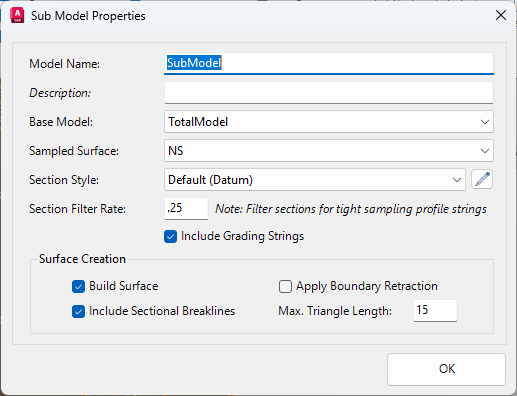
Create Sub Model |
Upon selecting the command the following form is displayed:
|
||||||||||||||||||||||||||||||||||||||||||||||||||||||||||||||||||||||||||||||||||||||||||||||||||||||||||||||||||||||||||||||||||||||
|
Model Properties |
Click to edit the properties of the currently Sub Model. See Create Sub Model for details. | ||||||||||||||||||||||||||||||||||||||||||||||||||||||||||||||||||||||||||||||||||||||||||||||||||||||||||||||||||||||||||||||||||||||
|
Display Panel |
|
||||||||||||||||||||||||||||||||||||||||||||||||||||||||||||||||||||||||||||||||||||||||||||||||||||||||||||||||||||||||||||||||||||||
|
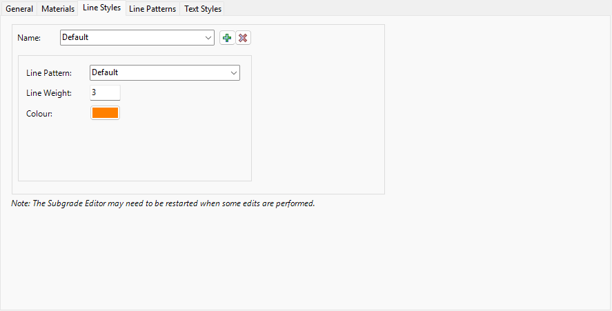
Style |
Set the style to control how the sub model is displayed. | ||||||||||||||||||||||||||||||||||||||||||||||||||||||||||||||||||||||||||||||||||||||||||||||||||||||||||||||||||||||||||||||||||||||
|
Regions |
If ticked on, | ||||||||||||||||||||||||||||||||||||||||||||||||||||||||||||||||||||||||||||||||||||||||||||||||||||||||||||||||||||||||||||||||||||||
|
Omitted Regions |
If ticked on, | ||||||||||||||||||||||||||||||||||||||||||||||||||||||||||||||||||||||||||||||||||||||||||||||||||||||||||||||||||||||||||||||||||||||
|
Sectional Breaklines |
If ticked on, sectional breaklines are displayed. | ||||||||||||||||||||||||||||||||||||||||||||||||||||||||||||||||||||||||||||||||||||||||||||||||||||||||||||||||||||||||||||||||||||||
|
Linear Breaklines |
If ticked on, linear breaklines are displayed. | ||||||||||||||||||||||||||||||||||||||||||||||||||||||||||||||||||||||||||||||||||||||||||||||||||||||||||||||||||||||||||||||||||||||
|
Omitted Breaklines |
If ticked on, breaklines that have been omitted from the sub model are displayed. | ||||||||||||||||||||||||||||||||||||||||||||||||||||||||||||||||||||||||||||||||||||||||||||||||||||||||||||||||||||||||||||||||||||||
|
Existing Surface |
If ticked on, the existing surface is displayed at each section. | ||||||||||||||||||||||||||||||||||||||||||||||||||||||||||||||||||||||||||||||||||||||||||||||||||||||||||||||||||||||||||||||||||||||
|
Design Surface |
If ticked on, the design or base surface is displayed at each section. | ||||||||||||||||||||||||||||||||||||||||||||||||||||||||||||||||||||||||||||||||||||||||||||||||||||||||||||||||||||||||||||||||||||||
|
Subgrade Surface |
If ticked on, the subgrade surface is displayed. | ||||||||||||||||||||||||||||||||||||||||||||||||||||||||||||||||||||||||||||||||||||||||||||||||||||||||||||||||||||||||||||||||||||||
|
Station Labels |
If ticked on, station labels are displayed at each section. | ||||||||||||||||||||||||||||||||||||||||||||||||||||||||||||||||||||||||||||||||||||||||||||||||||||||||||||||||||||||||||||||||||||||
|
Section Labels |
If ticked on, labels are displayed for materials and depths at each section. | ||||||||||||||||||||||||||||||||||||||||||||||||||||||||||||||||||||||||||||||||||||||||||||||||||||||||||||||||||||||||||||||||||||||
|
String Labels |
If ticked on, labels are displayed with the string names. | ||||||||||||||||||||||||||||||||||||||||||||||||||||||||||||||||||||||||||||||||||||||||||||||||||||||||||||||||||||||||||||||||||||||
|
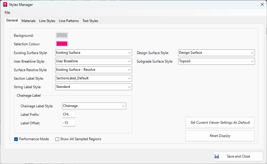
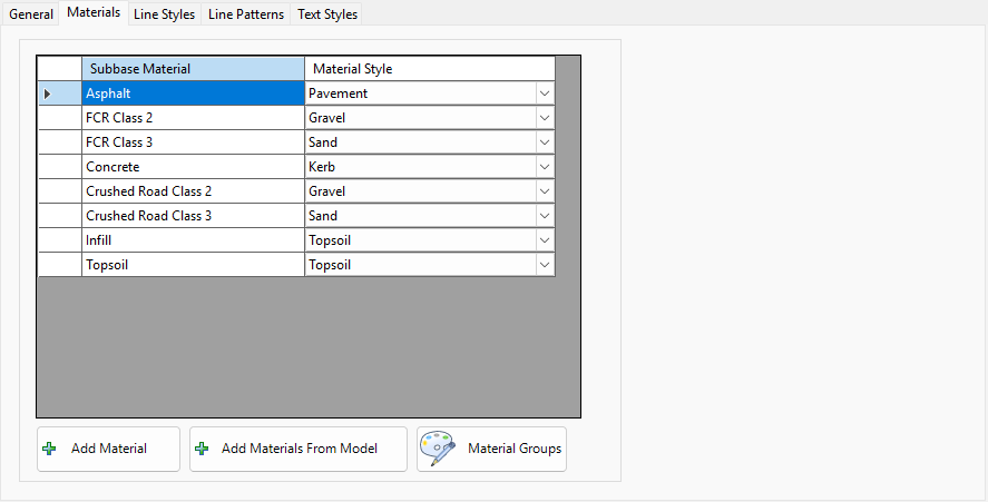
Display Manager |
Upon selecting the command the following form is displayed:
|
||||||||||||||||||||||||||||||||||||||||||||||||||||||||||||||||||||||||||||||||||||||||||||||||||||||||||||||||||||||||||||||||||||||
|
Tools Tab |
Includes tools for managing the calculation of the sub model.
|
||||||||||||||||||||||||||||||||||||||||||||||||||||||||||||||||||||||||||||||||||||||||||||||||||||||||||||||||||||||||||||||||||||||
|
Tools Panel |
Contains tools to edit and reset the Subgrade Model. |
||||||||||||||||||||||||||||||||||||||||||||||||||||||||||||||||||||||||||||||||||||||||||||||||||||||||||||||||||||||||||||||||||||||
|
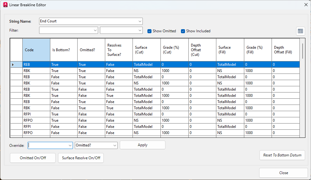
Linear Breakline Editor |
Click to open the Linear Breakline Editor form:
|
||||||||||||||||||||||||||||||||||||||||||||||||||||||||||||||||||||||||||||||||||||||||||||||||||||||||||||||||||||||||||||||||||||||
|
Compute Section Style |
Click to reset all strings to the current Section Style. The following form is displayed:
|
||||||||||||||||||||||||||||||||||||||||||||||||||||||||||||||||||||||||||||||||||||||||||||||||||||||||||||||||||||||||||||||||||||||
|
Reset All (Bottom Datum) |
Click to reset all strings to use the bottom datum. The following form is displayed:
|
||||||||||||||||||||||||||||||||||||||||||||||||||||||||||||||||||||||||||||||||||||||||||||||||||||||||||||||||||||||||||||||||||||||
|
Reset Surface Resolve |
Click to reset surface resolve parameters for all strings. The following form is displayed:
|
||||||||||||||||||||||||||||||||||||||||||||||||||||||||||||||||||||||||||||||||||||||||||||||||||||||||||||||||||||||||||||||||||||||
|
Styles Panel |
|
||||||||||||||||||||||||||||||||||||||||||||||||||||||||||||||||||||||||||||||||||||||||||||||||||||||||||||||||||||||||||||||||||||||
|
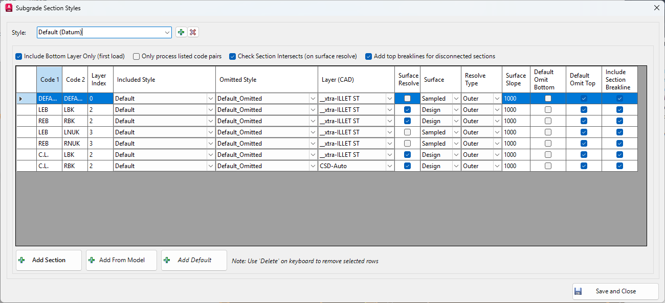
Section Style |
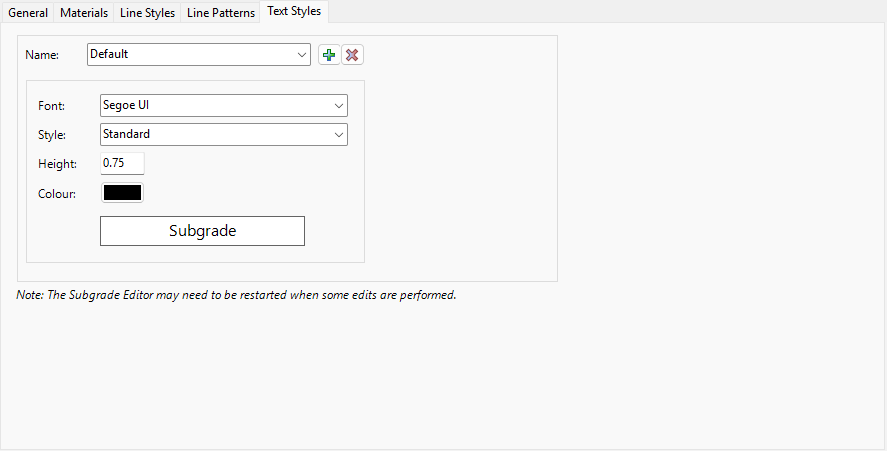
Click to open the Subgrade Section Styles form:
|
||||||||||||||||||||||||||||||||||||||||||||||||||||||||||||||||||||||||||||||||||||||||||||||||||||||||||||||||||||||||||||||||||||||
|
View Tab |
Includes controls for managing the display of cross sections
|
||||||||||||||||||||||||||||||||||||||||||||||||||||||||||||||||||||||||||||||||||||||||||||||||||||||||||||||||||||||||||||||||||||||
|
String Name |
Select the string to view. | ||||||||||||||||||||||||||||||||||||||||||||||||||||||||||||||||||||||||||||||||||||||||||||||||||||||||||||||||||||||||||||||||||||||
|
Station |
Select a station to view the cross section. | ||||||||||||||||||||||||||||||||||||||||||||||||||||||||||||||||||||||||||||||||||||||||||||||||||||||||||||||||||||||||||||||||||||||
|
Camera Length |
|||||||||||||||||||||||||||||||||||||||||||||||||||||||||||||||||||||||||||||||||||||||||||||||||||||||||||||||||||||||||||||||||||||||
|
Camera Height |
Type to set the height of the camera. | ||||||||||||||||||||||||||||||||||||||||||||||||||||||||||||||||||||||||||||||||||||||||||||||||||||||||||||||||||||||||||||||||||||||
|
Previous |
Click to view the previous cross section. | ||||||||||||||||||||||||||||||||||||||||||||||||||||||||||||||||||||||||||||||||||||||||||||||||||||||||||||||||||||||||||||||||||||||
|
Next |
Click to view the next cross section. | ||||||||||||||||||||||||||||||||||||||||||||||||||||||||||||||||||||||||||||||||||||||||||||||||||||||||||||||||||||||||||||||||||||||
|
Import Tab |
Includes core controls for managing the display and general operations
|
||||||||||||||||||||||||||||||||||||||||||||||||||||||||||||||||||||||||||||||||||||||||||||||||||||||||||||||||||||||||||||||||||||||
|
Pipe Networks Panel |
|
||||||||||||||||||||||||||||||||||||||||||||||||||||||||||||||||||||||||||||||||||||||||||||||||||||||||||||||||||||||||||||||||||||||
|
Show Pipe Networks |
If ticked on, Pipe Networks are displayed in the Subgrade Model Manager graphical window. | ||||||||||||||||||||||||||||||||||||||||||||||||||||||||||||||||||||||||||||||||||||||||||||||||||||||||||||||||||||||||||||||||||||||
|
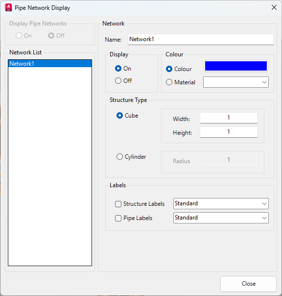
Setup Pipe Networks |
Click to open the Pipe Network Display form:
|
||||||||||||||||||||||||||||||||||||||||||||||||||||||||||||||||||||||||||||||||||||||||||||||||||||||||||||||||||||||||||||||||||||||
|
External Files Panel |
|
||||||||||||||||||||||||||||||||||||||||||||||||||||||||||||||||||||||||||||||||||||||||||||||||||||||||||||||||||||||||||||||||||||||
|
Import CAD |
|||||||||||||||||||||||||||||||||||||||||||||||||||||||||||||||||||||||||||||||||||||||||||||||||||||||||||||||||||||||||||||||||||||||
|
Load CAD |
|||||||||||||||||||||||||||||||||||||||||||||||||||||||||||||||||||||||||||||||||||||||||||||||||||||||||||||||||||||||||||||||||||||||
|
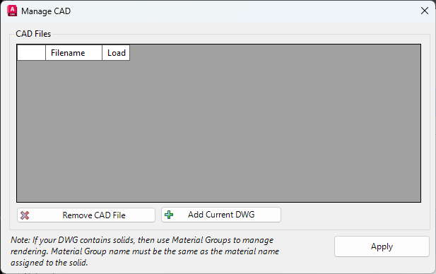
Manage CAD |
Click to open the Manage CAD form:
|
||||||||||||||||||||||||||||||||||||||||||||||||||||||||||||||||||||||||||||||||||||||||||||||||||||||||||||||||||||||||||||||||||||||
|
Unload CAD |
|||||||||||||||||||||||||||||||||||||||||||||||||||||||||||||||||||||||||||||||||||||||||||||||||||||||||||||||||||||||||||||||||||||||
|
Export Tab |
Includes controls share data outside of Subgrade Model Manager.
|
||||||||||||||||||||||||||||||||||||||||||||||||||||||||||||||||||||||||||||||||||||||||||||||||||||||||||||||||||||||||||||||||||||||
|
General Panel |
|
||||||||||||||||||||||||||||||||||||||||||||||||||||||||||||||||||||||||||||||||||||||||||||||||||||||||||||||||||||||||||||||||||||||
|
Export |
Export the Sub Grade Model as a .obj, .stl, .las, .html, .pdf, .dwg or .dxf file. | ||||||||||||||||||||||||||||||||||||||||||||||||||||||||||||||||||||||||||||||||||||||||||||||||||||||||||||||||||||||||||||||||||||||
|
CAD Panel |
|
||||||||||||||||||||||||||||||||||||||||||||||||||||||||||||||||||||||||||||||||||||||||||||||||||||||||||||||||||||||||||||||||||||||
|
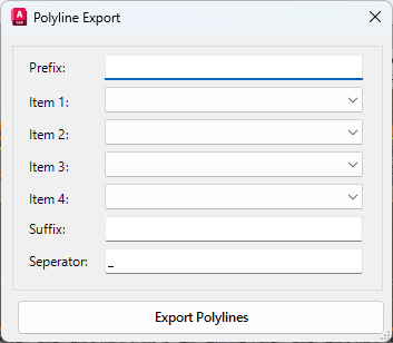
Polyline Export |
Click to open the Polyline Export form:
|
||||||||||||||||||||||||||||||||||||||||||||||||||||||||||||||||||||||||||||||||||||||||||||||||||||||||||||||||||||||||||||||||||||||
|
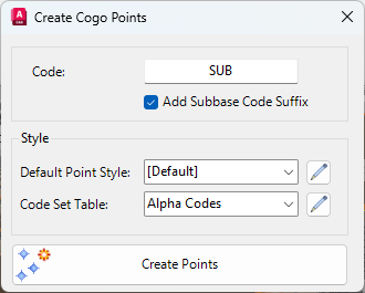
COGO Point Stakeout |
Click to open the Create Cogo Points form:
|
||||||||||||||||||||||||||||||||||||||||||||||||||||||||||||||||||||||||||||||||||||||||||||||||||||||||||||||||||||||||||||||||||||||
|
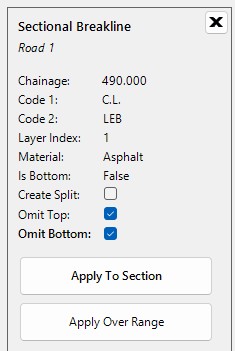
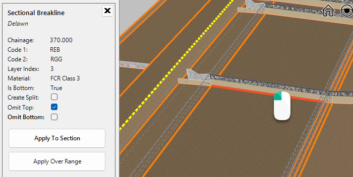
Sectional Breakline |
Graphically select a Sectional Breakline to display the Sectional Breakline Panel.
|
||||||||||||||||||||||||||||||||||||||||||||||||||||||||||||||||||||||||||||||||||||||||||||||||||||||||||||||||||||||||||||||||||||||
|
Station |
Displays the station of the breakline along the string. | ||||||||||||||||||||||||||||||||||||||||||||||||||||||||||||||||||||||||||||||||||||||||||||||||||||||||||||||||||||||||||||||||||||||
|
Code 1 |
Displays the first Code. | ||||||||||||||||||||||||||||||||||||||||||||||||||||||||||||||||||||||||||||||||||||||||||||||||||||||||||||||||||||||||||||||||||||||
|
Code 2 |
Displays the second Code. | ||||||||||||||||||||||||||||||||||||||||||||||||||||||||||||||||||||||||||||||||||||||||||||||||||||||||||||||||||||||||||||||||||||||
|
Layer Index |
|||||||||||||||||||||||||||||||||||||||||||||||||||||||||||||||||||||||||||||||||||||||||||||||||||||||||||||||||||||||||||||||||||||||
|
Material |
Displays the material assigned. | ||||||||||||||||||||||||||||||||||||||||||||||||||||||||||||||||||||||||||||||||||||||||||||||||||||||||||||||||||||||||||||||||||||||
|
Is Bottom |
Indicates whether the selected breakline is the datum. | ||||||||||||||||||||||||||||||||||||||||||||||||||||||||||||||||||||||||||||||||||||||||||||||||||||||||||||||||||||||||||||||||||||||
|
Create Split |
|||||||||||||||||||||||||||||||||||||||||||||||||||||||||||||||||||||||||||||||||||||||||||||||||||||||||||||||||||||||||||||||||||||||
|
Omit Top |
|||||||||||||||||||||||||||||||||||||||||||||||||||||||||||||||||||||||||||||||||||||||||||||||||||||||||||||||||||||||||||||||||||||||
|
Omit Bottom |
|||||||||||||||||||||||||||||||||||||||||||||||||||||||||||||||||||||||||||||||||||||||||||||||||||||||||||||||||||||||||||||||||||||||
|
Apply to Selection |
Click to apply the changes made in the panel to the selected sectional breakline. | ||||||||||||||||||||||||||||||||||||||||||||||||||||||||||||||||||||||||||||||||||||||||||||||||||||||||||||||||||||||||||||||||||||||
|
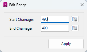
Apply Over Range |
Click to apply the changes made to sectional breaklines over a range of stations. The following form is displayed:
|
||||||||||||||||||||||||||||||||||||||||||||||||||||||||||||||||||||||||||||||||||||||||||||||||||||||||||||||||||||||||||||||||||||||
|
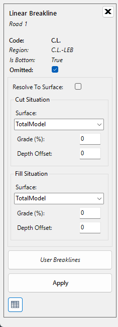
Linear Breakline |
Graphically select a Linear Breakline to display the Linear Breakline Panel.
|
||||||||||||||||||||||||||||||||||||||||||||||||||||||||||||||||||||||||||||||||||||||||||||||||||||||||||||||||||||||||||||||||||||||
|
Code |
|||||||||||||||||||||||||||||||||||||||||||||||||||||||||||||||||||||||||||||||||||||||||||||||||||||||||||||||||||||||||||||||||||||||
|
Region |
|||||||||||||||||||||||||||||||||||||||||||||||||||||||||||||||||||||||||||||||||||||||||||||||||||||||||||||||||||||||||||||||||||||||
|
Is Bottom |
Indicates whether the selected breakline is the datum. | ||||||||||||||||||||||||||||||||||||||||||||||||||||||||||||||||||||||||||||||||||||||||||||||||||||||||||||||||||||||||||||||||||||||
|
Omitted |
|||||||||||||||||||||||||||||||||||||||||||||||||||||||||||||||||||||||||||||||||||||||||||||||||||||||||||||||||||||||||||||||||||||||
|
Resolve To Surface |
|||||||||||||||||||||||||||||||||||||||||||||||||||||||||||||||||||||||||||||||||||||||||||||||||||||||||||||||||||||||||||||||||||||||
|
Cut Situation Panel |
Set the parameters for surface resolve in Cut situations. |
||||||||||||||||||||||||||||||||||||||||||||||||||||||||||||||||||||||||||||||||||||||||||||||||||||||||||||||||||||||||||||||||||||||
|
Surface |
Select the surface to resolve to. | ||||||||||||||||||||||||||||||||||||||||||||||||||||||||||||||||||||||||||||||||||||||||||||||||||||||||||||||||||||||||||||||||||||||
|
Grade (%) |
Type to set the grade for the surface resolve. | ||||||||||||||||||||||||||||||||||||||||||||||||||||||||||||||||||||||||||||||||||||||||||||||||||||||||||||||||||||||||||||||||||||||
|
Depth Offset |
|||||||||||||||||||||||||||||||||||||||||||||||||||||||||||||||||||||||||||||||||||||||||||||||||||||||||||||||||||||||||||||||||||||||
|
Fill Situation Panel |
Set the parameters for surface resolve in Fill situations. |
||||||||||||||||||||||||||||||||||||||||||||||||||||||||||||||||||||||||||||||||||||||||||||||||||||||||||||||||||||||||||||||||||||||
|
Surface |
Select the surface to resolve to. | ||||||||||||||||||||||||||||||||||||||||||||||||||||||||||||||||||||||||||||||||||||||||||||||||||||||||||||||||||||||||||||||||||||||
|
Grade (%) |
Type to set the grade for the surface resolve. | ||||||||||||||||||||||||||||||||||||||||||||||||||||||||||||||||||||||||||||||||||||||||||||||||||||||||||||||||||||||||||||||||||||||
|
Depth Offset |
|||||||||||||||||||||||||||||||||||||||||||||||||||||||||||||||||||||||||||||||||||||||||||||||||||||||||||||||||||||||||||||||||||||||
|
User Breaklines |
|
||||||||||||||||||||||||||||||||||||||||||||||||||||||||||||||||||||||||||||||||||||||||||||||||||||||||||||||||||||||||||||||||||||||
|
Apply |
Click to apply changes to the selected Sectional Breakline. | ||||||||||||||||||||||||||||||||||||||||||||||||||||||||||||||||||||||||||||||||||||||||||||||||||||||||||||||||||||||||||||||||||||||
|
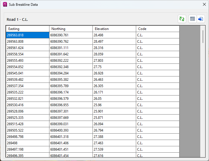
Sub Breakline Data |
Click to open the Sub Breakline Data form. | ||||||||||||||||||||||||||||||||||||||||||||||||||||||||||||||||||||||||||||||||||||||||||||||||||||||||||||||||||||||||||||||||||||||