Icon:


Icon: |
|
FastTrack AI assesses alignments in the drawing to predict how those alignments should be used in string based design, and provides a natural language input to describe how you would like to proceed with using the alignments and building models.
FastTrack AI lets you describe your project in plain English (or your supported language) and automatically configures CSD strings, road associations, templates, and action options. Instead of manually clicking through dozens of dialog boxes, you tell FastTrack what you are trying to achieve, and the AI translates that into a structured execution plan.
FastTrack analyses:
Using this information, together with a Large Language Model (LLM), FastTrack proposes:
FastTrack does not apply changes immediately. Instead, it presents a structured workflow plan (in the Current Plan panel) showing:
Click Apply & Build Workflow to open the Workflow interface. Any value displayed in the Workflow interface can be reviewed and edited before the design is created.
The Legacy Option bypasses the natural language input and reverts to machine learning to assess both the alignment name and geometry to recommend alignment usage. FastTrack AI Legacy learns based on the confirmed alignment usage.
After the alignment usage is determined (via natural language AI prediction or Legacy machine learning), FastTrack AI then proceeds to build a Workflow to relate all those alignments to each other to: generate strings, apply templates, add variations and batter/daylight overrides, add section sampling, build models and create a Thread. The Workflow form describes the processes that FastTrack AI will apply to build the models, with the user able to make changes to strings and the associations between alignments and strings.
FastTrack AI speeds up the creation of strings, application of variations and building of Models, letting the user focus on the vertical design and production outputs. FastTrack AI also simplifies many processes that would be undertaken manually, by summarising how alignments could be used and simplifying the creation inputs.
FastTrack AI can be operated at any time through the lifecycle of the project, so users are encouraged to start small and build up the design controls by adding more alignments and running FastTrack AI. Any alignments already used to create a string or used as a Road section control will not be shown again in FastTrack AI.
Common Road String controls are well supported, such as for including saw cuts, left/right pavement edge controls, footpath alignments and property edge/extent of works limits.
Independent string control can also be applied and automatically included in a Model, with the added ability to adopt elevations from a surface model.
Islands (including to define roundabouts) are also supported - these are 'cut' into the base design model and a new Built Model is created to incorporate them.
Existing (non designed) features can be included to facilitate connection with designed strings. The expectation is that 'Existing' features described in FastTrack AI will enable intersection connections to apply (kerb returns and road string elevation matching).
On each operation, FastTrack AI will create a Thread, uniquely named (or named by the user). The Thread contains the list of commands applied to each string and construction of Models, allowing for rapid recalculation of multiple activities that generated the original results.
To fully appreciate the processes of Project Assist and the approaches to different design scenarios, it is recommended to review videos stored at the following link:
FastTrack AI offers two modes of use:
AI Reasoning Mode: An initial assessment of the alignment is made using AI and the user prompts how to use the alignments, following which the AI develops an actionaable workflow
Legacy Machine Learning Mode: applies learned behaviour to assess how users want to use alignments. Based on geometry and the alignment names, FastTrack AI will suggest how the alignment is intended to be used in design. It learns from the way each user names alignments - every time FastTrack AI is run it will learn from the outcomes of the previous operation and modify it's behaviour. What this means is that, over time, consistent alignment naming conventions will result in the correct alignment types being applied on new projects.
FastTrack AI can be run multiple times in the lifecycle of a project, and operates on the following basis:
An 'existing' surface has been created in the drawing and describes the shape of the existing terrain. All Strings created in FastTrack AI will need to reference a base (existing) surface
At least one alignment has been created, describing a design feature for the project. Users are encouraged to create multiple alignments.
Users are encouraged to create multiple alignments for controlling different aspects of a design, such as:
For Road Strings, alignments describe the centreline of the string. Edits can be applied to the Road Strings by the inclusion of additional alignments, including:
Alignments that describe the edge of the Road Edge (the Code to apply to is as defined in the Active Drawing Settings > Design Settings > Default Point Code Intersection Connections)
Alignments that attach to a Road Edge but need to be modelled as a separate string with cross sections (such as 90 degree angle parking bays, or a car park that connects to the edge of a Road).
Alignments that describe the footpath/sidewalk, for horizontal and/or vertical control
Alignments that describe a pavement saw cut, usually added to enable road widening (the cut is placed at the edge of the existing pavement, with the intent to extend with new pavement to increase the overall road width)
Alignments that describe the Property Boundary or extents of the design
For Kerb Returns and Cul-de-sacs. Initially added as a Road Edge or String Control, ticking on Kerb Return or Cul-de-sac will set the alignment to be created as a kerb return or cul-de-sac string.
For independent string design of features such as dish drains draped onto the existing/design surface, or other features that are designed somewhat independently of any other network (Road, Kerb) string cross sections. For these cases, the alignment is NOT associated with a Road String
For including islands (as well as roundabout island strings). When an Island is selected as the string type, the software will initially match elevations to the base design model, then create a new Model that includes the islands and removes any codes that conflict with the island (like a paste, islands typically sit on top of other designs. Like a paste, they often replace designed strings/codes. A common case is a median island sitting on top of a designed road, where the median straddles the original road centreline)
For emulating Existing (no Design) Roads
These are included to allow the designed elements to match into existing features that are not being designed (such as a designed road finishing at the edge of an existing road, or redesigning a road and needing to blend the kerb returns back to an existing side road).
These are not intended to be used in any design capacity, except to facilitate connection of designed strings back to existing elevations. All 'Existing' type features will have their elevations matched to the existing surface
Alignments that describe Existing Road Centrelines (the software enables connection of kerb returns and designed roads to the centreline). When a centreline is used, a Template can be applied, and the road edges and footpaths can be associated with alignments and matched to the existing surface elevations. This is very useful for the cases where existing side roads need to reconnect with designed main (continuous) roads
Alignments that describe existing road edges (these can be used to control widths for an Existing Road Centreline OR provide direct connections for incoming designed roads, including enabling kerb return creation)
Alignments that describe existing footpaths/sidewalks (these can be used to control widths for the existing footpath/sidewalk locations and are usually associated with an Existing Road Centreline string).
FastTrack AI will create up to three Built Models, pending the user requirements for the design:
Total Model
Roads, kerb returns and cul-de-sacs can all be included in an automated model called TotalModel. This model will automatically trim the Roads to accommodate the inclusion of kerb returns and cul-de-sacs.
FastTrack AI will create this model when users add Roads with Variations (widen to alignment, match codes to strings) and Batter Overrides, as well as Kerb Returns and Cul-de-sacs
Design Model
The addition of independent strings, including strings connected to the road edge (for a parking bay, as an example) or the footpath (where the footpath is best described with it's own cross sections) will result in the creation of a Design Model (Built Model)
TotalModel is used as a base. Codes are removed to include the Strings.
Design Model with Islands included
The addition of islands (islands are typically draped onto the base design model) will result in the creation of another Built Model.
Independent Strings that are set to drape (adopt elevations from) the Design Model
The Design Model is used as a base and then edited to include the islands and trim out overlapping codes from the base model
The Intersection Manager can be used to set up the kerb returns at each intersection, as well as omit the kerb batters and set all intersections as all-crowned intersections (remove Main Road edge).
Road Edge. A Code included in Road String cross sections that typically represents the edge of the road pavement. This is the Code that other strings connect to (such as kerb/curb returns, cul-de-sacs, side roads, etc.).
It is defined in the Active Drawing Settings form > Design Settings > Default Point Code Intersection Connections > Matching Code for Kerbs.
Saw Cut. A Code included in Road String cross sections that typically describe the place where the existing pavement is cut and new pavement is attached. At this point there may be an allowance for a crossfall change, or there may be a requirement to maintain a single road pavement crossfall from the centreline to the Road Edge.
The expected Codes are as described in the Project Assist Settings form > Default Codes tab (Sawcut).
Footpath. A Code included in Road String cross sections that typically describes a footpath/sidewalk. This is assumed to be described using two codes (inside edge and outside edge).
The expected Codes are as described in the Project Assist Settings form > Default Codes tab (Footpath inner and Footpath outer).
Boundary. A Code included in Road String cross sections that typically describe the property boundary location.
The expected Codes are as described in the Project Assist Settings form > Default Codes tab (Boundary).
When FastTrack AI is first run, the user is prompted to establish some core settings/behaviours for FastTrack AI:
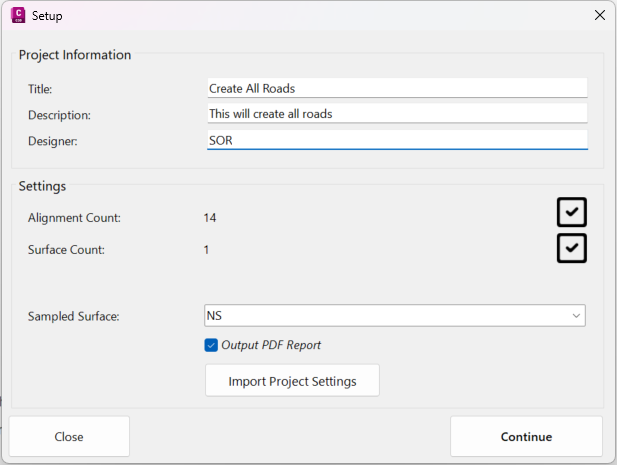
Project Information. Here users can set the project name, description and designer. This information is included in the output PDF Report that FastTrack AI creates
Settings. This lists the number of alignments and surfaces that are available in the project. Most importantly it is here that the user sets the Sampled Surface. The Sampled Surface is considered to be the existing ground surface for all strings. The user can also import project settings that have been previously saved.
If it is required to change these settings after first run of FastTrack AI, there is a command menu item in the Workflow to reopen this form (File > Project Settings).
Users can toggle ot output a HTML or PDF report of all actions applied by FastTrack.
The report details every action taken and includes links to video resources describing how the actions are manually applied in the software. The Project Information is included in the report.
This is a complete list of all actions taken on all strings and models, to generate the final result.
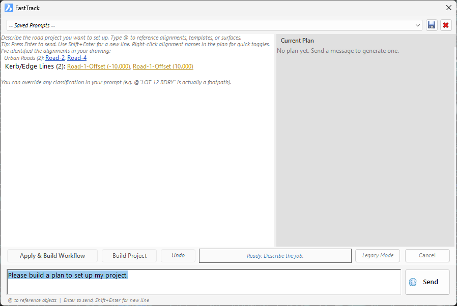
An Artificial Intellgience agent assesses the alignments to predict usage of alignments in the drawing.
The form is split into sections:
Bottom section: here you prompt for how you want to use alignments. Click Send to update the Plan for how alignments will be used in a model. The initial assessment from the AI needs to be confirmed via the prompt before a Plan is established (you can only execute on a plan). Use Build Project to immediately build the Current Plan, or click Apply & Build Workflow for a final review/edit before proceeding to create the model
Left panel: This contains your conversation with the AI and includes the initial AI assessment of alignments, the requests you have made and the AI responses to build/update the plan. Users can also right click on any alignment (where shown with underline) to request changes via a shortcut menu (eg: change template) - the selections are automatically sent to the prompt, to be Sent to update the Current Plan.
Right panel: This is the Current Plan (what is set to be executed in the drawing). Users can also right click on any alignment (where shown with underline) to request changes via a shortcut menu (eg: change template) - the selections are automatically sent to the prompt, to be Sent to update the Current Plan
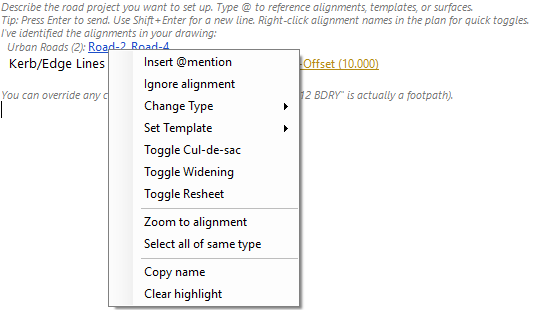
Users can right click on an underlined alignment to add to the prompt with intstructions to edit the plan:
While typing, use the @ symbol to access a list of Alignments, Templates and Intersections to reference in your prompt.
As well as establishing alignment usage and behaviour, intersection kerb returns can be defined. These can be done overall as well as per intersection. Type @ to pick an alignment from the list and set specific kerb return radii for the selected intersection. Click Send to see these in the Current Plan.
As Prompts are input by the user and the Send button is pressed, the AI LLM will analyse the requests, reason how to apply these to the alignment/s and the add these to the Current Plan (RHS panel).
Once the Current Plan describes the requirements, there are two options to proceed and create the Model/s:
Apply and Build Workflow - this moves you to the Workflow section to confirm selections, edit and choose how associated alignments are applied
Build Project - move directly to building the project using the AI recommendations
If it is desired to resort to the machine-learning method to assess alignments and proceed to the workflow section, click on the Legacy button.
The Legacy method process is as per below:
Identifies the intended usage of the alignment (e.g.: Road string, road edge control, existing road CL, etc.). Users can select alignments and change the usage. This is managed via the Alignment Usage form.
After this, users can proceed to the workflow form to then create the model/s.
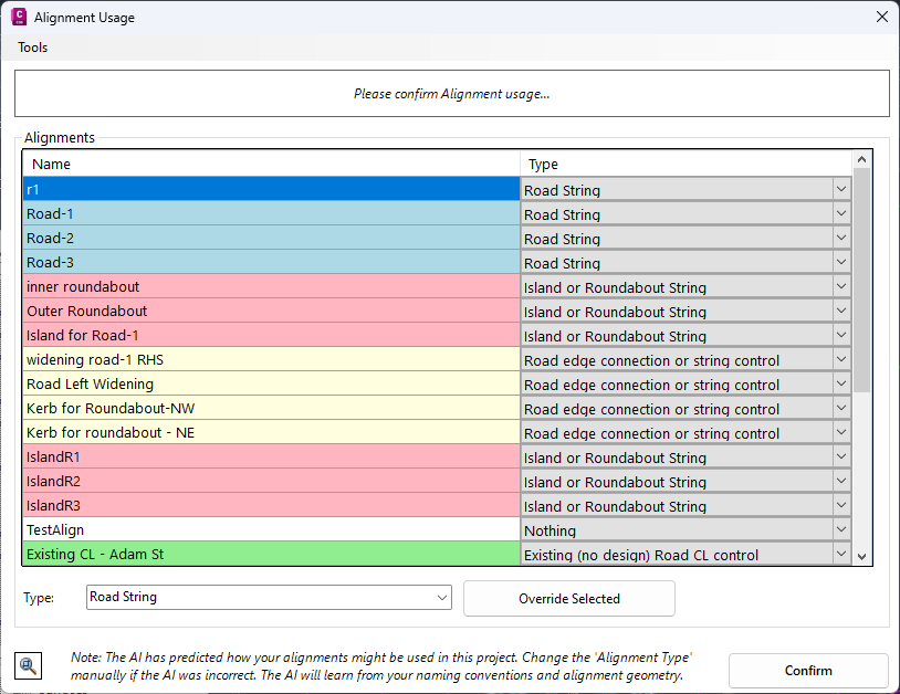
FastTrack AI predicts the alignment usage based on the alignment name and geometry. Use the pick list to change how the alignment should be used.
As the mouse is hovered over each Alignment Name, a highlight will display in the drawing over the alignment, coloured based on the assigned Type.
Information about the intent of each Alignment Type is provided at the top of this form.
Note: The software learns from each use, so applying consistent alignment naming structures and setting the Type will teach FastTrack AI what different alignments are to be used for (what Type to set).
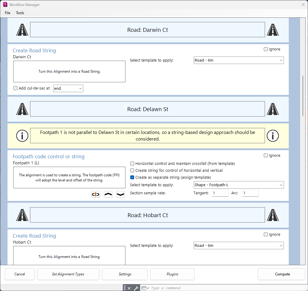
This is the core of FastTrack AI - it is where the decisions are finally made about the structuring of the data.
The Workflow is built with Panels - each Panel describes actions and information for each alignment.
Depending on the alignment usage, options on how to use an alignment will differ.
Road Strings are denoted by a light blue Panel with the Road name and this symbol: 
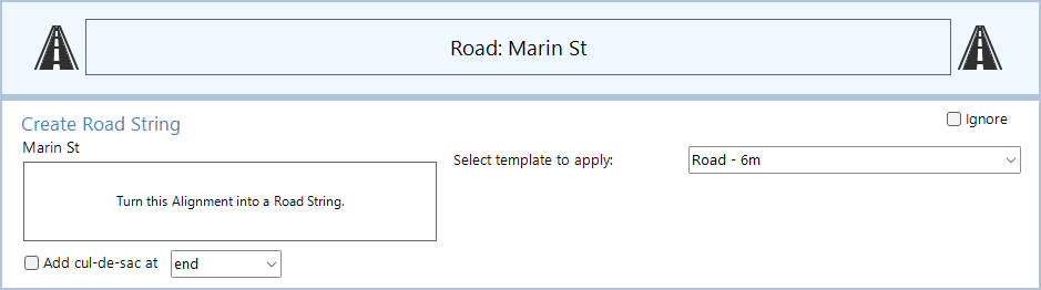
Under the Road String Panel will be the basic creation tools for the Road. Assign the Template, select if the Road should behave as a Resheet or Road Widening (these options only display subject to associated alignments being included). Alignment requirements for triggering a Resheet or Road Widening option are:
for Resheet, at least two alignments are needed that define the left and right road edges
for a Road Widening four alignments are needed (saw cut and road edge alignments left and right of the road centreline).
Click on a Road String panel to collapse all displayed alignments associated with that Road String. Click again to expand.
Warning/Information message panels may display in the Workflow to advise users of certain actions that FastTrack AI has taken, or to explain why FastTrack AI has defaulted to a suggested application for the alignment.
Warning/Informational messages display with a yellow background and appear similar to this:

The above information messaging is explaining why a user may consider a particular method for using an alignment that describes a road edge, and the sets this as the default selection (with the user able to override that selection).
There are a number of cases where alignments are not shown in the Workflow, even though they are being used (such as workflow selections that force a certain action for associated alignments). In these cases, the user will see an information message advising that the alignment/s are being used. Some typical cases where alignments are displayed in the Alignment Usage form and then are not displayed in the Workflow:
Road Resheet. This option is available for a Road String, where two Road Edge alignments (left and right of a Road String) are associated to the Road. define the Road String as a 'Resheet' road reconstruction project. In this case, the left and right alignments are automatically used by the Road String to control the left and right road edge offsets and to be used in establishing the road centreline elevations (in a Resheet application, applied via the Auto Profile form in the Vertical Grading Editor, the software will move the centreline up/down to ensure a minimum pavement thickness between two alignments, the left and right edge)
Road Widening. This option is available for a Road String, where two Saw Cut alignments and two Road Edge alignments are associated to the Road
Existing Roads. Where there are additional Alignments for an 'Existing Road' (this is a String that is included in Design usually for the sole purpose of supporting intersection connections. It is assumed these have no design elements) then a warning message will display to advise these alignments are being used by the Existing Road CL. In the Alignment Usage form, users can have the Existing Road CL, as well as road edge controls and footpath/sidewalk controls. Only the Existing Road CL will display as the others are assumed to be used in the cross sections of the Road String (variations will apply to set the road edge codes to match the surface and use the alignments, and the footpath/sidewalk as well where assigned.
Many different alignment types can be associated with the road string and will be listed under the Road String panel, if they are associated to that Road.
Alignments that can be used to control a Road String include: road edge widening, saw cuts, footpaths/sidewalks, boundaries/batters/daylights. To achieve these outcomes, they must be Associated with that Road.
Typically, FastTrack AI will automatically make the Road String association based on alignment geometry (proximity to the Road String, alignment type and having similar directions.
General characteristics of an associated Road String are as follows:

Highlighted in pink in above is the type of alignment/string control.
Highlighted in Yellow is confirmation of what Road String it is associated with as well as what Side it is located on (left or right).
Highlighted in Purple is the associate/disassociate button  - clicking on this button will remove the string/s association to a Road.
Disassociated Strings will be placed under the 'Alignments not associated with roads' panel.
If the String is disassociated, clicking this button will let the user pick a Road String to associate with (the alignment can then be used to modify the cross sections of the selected Road String)
The up and down arrows can be used to reorder the panels. Each panel is process in order in the Workflow.
When strings are associated to a Road, the Road String cross sections are affected even when users elect to create as a separate string (as shown above). Normally, what happens is that Codes are removed from the Road cross sections to enable the String cross sections to take control over those ranges. Let's consider two cases:
If an alignment is acting as a Road Edge Connection with full independent string control (with independent cross sections), then the Road String cross sections will be removed, from the edge road code (as defined in the Active Drawing Settings - default would be EB or ETW) outwards. It is assumed that the String being added will describe the elements working outside from the road edge code
If an alignment is acting as a Footpath/Sidewalk with full independent string control (with independent cross sections), then the Road String cross section codes for the footpath/sidewalk will be removed. It is assumed that the String being added will describe the cross sections of the footpath/sidewalk
The available inputs will differ per alignment type - see below for input controls for different string/alignment types.
Alignments/Strings not associated with a Road will be listed under this panel in the Workflow:

Any alignment type can be disassociated from a Road String and behave as an independent string (with it's own cross section controls and added to the Design Model built model).
Alignments being used as Island Strings, as well as Existing Road type alignments, will be listed automatically as not being associated with a Road.
Note: Kerb returns may also be listed here, but will behave as Kerb Returns in the TotalModel regardless of the road association status.
The available inputs will different per alignment type - see below for input controls for different string types.
After the specific string and alignment controls are defined, some standard (overall actions) can be applied. These are separated into different panels:
Intersections

This will create kerb returns at intersections. There are some configuration items included here such as the radius, omitting batters and creating intersections that maintain the crowns of both roads (Remove main road edges). Then the main road edges are removed, the kerb return pavement extends to the main road centreline instead of the main road edge (so the kerb return vertical design will control the pavement crossfall of the main road).
Click on the Intersection Manager button to enable full edit control of each kerb return at each intersection to be established before creation.
Create Model Builder Model

FastTrack AI creates Built Models pending the user selections for how to use the alignments. Here users can change the names of the models to create, or select to add the FastTrack AI controls to an existing model.
Note: Any entries added by FastTrack AI will be flagged in Model Builder
Build Design Models

This final action is to build all models, as per the configuration under Create Model Builder model as well as the TotalModel (Auto Model command) surface.
Type in a Min, Triangle Length and tick on Use Boundary Retraction to create a boundary by trimming triangles working from outside in.
In the workflow, any alignment or action can be ignored from processing. When Ignore is ticked on, the String (and in the case of a Road String, all associated alignments) the panel actions will not be included.

When Ignore is ticked on, the event will be highlighted in pale yellow colour. All associated alignments to a Road String will also change colour and have Ignore ticked on.
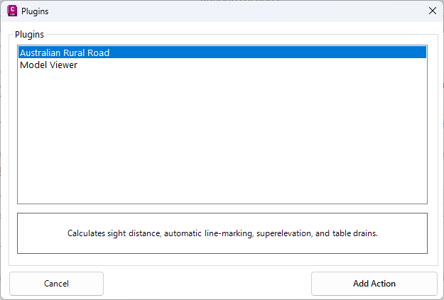
There is a 'Plugins' button at the bottom of the workflow:
Plugins are optional actions that can be added to the FastTrack AI processing. These are additional pieces of code (able to be created with .net) that provide extended functionality supported by the Civil Site Design API. When a Plugin is added, an additional panel will display in the workflow.
Some included with the software include:
Model Viewer
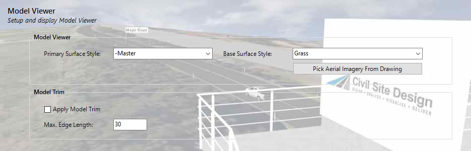
If added, another Panel will display in the workflow to facilitate setup of Model Viewer: Primary surface style, base surface style (with option to pick image from drawing)
A Model Trim action can also be applied. Tick on to apply - all built models created with Projet Assist will have the Model Trim action applied. See the Model Trim command for details on the inputs.
Australian Rural Road
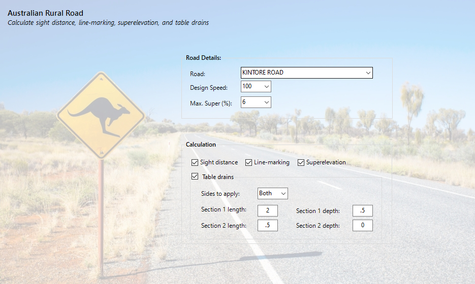
This is available for Australian customers only. It will apply superelevation to the selected road based on the design speed and maximum superelevation. There are also options to create sight distance checks, add centreline linemarking based on the sight distance results and add Table Drain entries (Design Data form) for the selected Road String.
See the Settings command for full details on the settings to guide the FastTrack AI workflow results. The settings established a number of default behaviours for FastTrack AI:
Default templates to apply for different string types, and sampling to apply
Default Codes to look for to associate with Saw Cuts, Footpath (inner and outer codes) and the Boundary.
Design constraint controls, for managing crossfalls
Defaults for creating cul-de-sacs
Built Model names to apply
Upon selecting the command the following form is displayed:
Project Settings displays on first start of FastTrack AI.
|
|
|
|
Project Information |
This information is provided at the top of the Output PDF Report |
|
Title |
Add a title for the project |
|
Description |
Add a description |
|
Designer |
Add the designer name |
|
Settings |
|
|
Alignment Count |
Lists the number of alignments available for FastTrack AI |
|
Surface Count |
Lists the number of surfaces in the drawing |
|
Sampled Surface |
Surface to use as the existing surface for created Strings |
|
Output HTML Report |
Tick on to include a HTML Report detailing all actions taken by Project Assist. |
|
Output PDF Report |
Tick on to include a PDF Report detailing all actions taken by Project Assist. |
| Import Project Settings | Select a FastTrack AI settings file (.dat) to apply. See FastTrack AI Settings form for more details. |
| Close | Exit the form |
|
Continue |
Proceed to the Alignment Usage form |
|
|
|
|
Prompt Picklist |
Pick a
pre-saved prompt to instruct the AI and how you would like to proceed
with using the alignments Use the Save button to save typed in prompts Use the X to delete saved prompts |
|
[Left Panel] |
Lists
the initial assessment from the LLM, the prompt requests from the user
and the LLM response to build the Current Plan. Users can right click on any underlined items to make changes. |
|
Prompt Input |
Type in the prompt for how to use the alignments in the drawing |
|
Prompt Input |
Type in the prompt for how to use the alignments in the drawing |
|
Prompt Input |
Type in the prompt for how to use the alignments in the drawing |
|
Analyse with AI |
Have the artificial intelligent engine build a plan using the alignments in the drawing and your prompt |
| Apply and build Workflow | Proceed to the Workflow Section |
| Build Project | Build directly from the analysis in the AI Analysis results |
| Legacy | Refer to the legacy mode for applying alignments in the FastTrack workflow (form details below) |
| Cancel | Exit |
| AI Analysis results | Reports available alignments in the drawing, initial assessment as well as the planned workflow based on analysis of your prompt. |
|
|
|||||||||||||||||||||
|
Information Frame |
The frame at the top provides information as the user hovers over the Alignment Names, explaining how the alignment type is used in a design | ||||||||||||||||||||
|
Alignments |
List of alignments and assigned usage Types | ||||||||||||||||||||
|
Name |
Name of each alignment that is not being used by Civil Site Design | ||||||||||||||||||||
|
Type |
Pick list for different alignment Types (how each is used in construction of a string based model in Civil Site Design). Input details are covered in the Workflow form details below. Note: Designated Footpath/Sidewalk Codes, Sawcut Codes and Boundary Line codes are assumed from the Settings. These need to match to the Codes applied to the associated Road String to enable variations to be applied to the Road String. Types include:
|
||||||||||||||||||||
|
Type |
Pick a type that could be applied to override selected alignments in the list | ||||||||||||||||||||
|
Override Selected |
Override all selected rows in the list. | ||||||||||||||||||||
|
|
Temporarily closes the form to enable zoom/pan in the drawing. Press esc to return to the form | ||||||||||||||||||||
|
Confirm |
Proceed to the Workflow form to generate the design strings, variations, additional sampling, models, surfaces and a Thread. | ||||||||||||||||||||
|
|
|||||||||||||||||||||||||||||||||||||
|
Menu Items |
|||||||||||||||||||||||||||||||||||||
|
File > Open Workflow |
The Workflow actions can all be saved and re-used when FastTrack AI is re-run. Use this command to open a form to enable selection and loading of a Saved Workflow | ||||||||||||||||||||||||||||||||||||
|
File > Save Workflow |
Saves all Workflow actions to file, for re-use on a subsequent run of FastTrack AI. A form will display for the workflow actions to be saved to file. Saved workflow files have extension .paw. | ||||||||||||||||||||||||||||||||||||
|
File > Project Settings |
Opens the Project Settings form. | ||||||||||||||||||||||||||||||||||||
|
Tools > Reset Workflow |
Restores all default settings in the workflow and removes all user edits in the workflow | ||||||||||||||||||||||||||||||||||||
|
Tools > Remove Associated Alignments (from Road) |
Select to disassociate all alignments from a select Road String. All associated alignments will move into the 'Alignments not associated with roads' panel. A confirmation form will display to apply this action and then the following form to select the Road to apply this action to: |
||||||||||||||||||||||||||||||||||||
|
Tools > Alignment List |
Opens a list of all used alignments (including those not displayed in the Workflow) to review and highlight in the drawing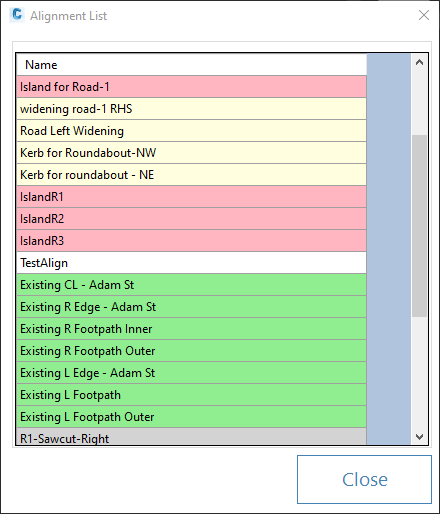 Hover over an alignment to highlight in the drawing. Click Close to close the form. |
||||||||||||||||||||||||||||||||||||
|
Tools > Set Thread Name (for current workflow) |
Every time FastTrack AI is run, it will create a Thread describing all the computations. By default, the thread is automatically named 'FastTrack AI Rebuild' with a unique identifier added at the end (e.g.: FastTrack AI Rebuild_3af9). Note: for the Road Assist command, FastTrack AI does not create a Thread. Use this command to uniquely name the Thread that will be created: 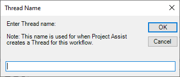 Type in a Thread name to use. |
||||||||||||||||||||||||||||||||||||
|
Workflow Panels |
Below is a list of each Workflow Panel. These match with the Alignment Usage Type | ||||||||||||||||||||||||||||||||||||
|
Road String Panels |
Details each Road String and associated alignments
|
||||||||||||||||||||||||||||||||||||
|
Road String |
|
||||||||||||||||||||||||||||||||||||
|
Road Edge Connection (or String control) |
|
||||||||||||||||||||||||||||||||||||
|
Footpath Control |
Can be used to control the offset, or offset and elevation, of the footpath/sidewalk. If created as a separate string the 'Footpath' codes (inner and outer) will be removed from the Road String to allow replacement by the separate 'Footpath' string and it's cross sections. It is assumed the Road String that the Footpath control is associated with has a Footpath (inner) Code (as per the Project Assist Settings - Footpath Templates)
|
||||||||||||||||||||||||||||||||||||
|
Sawcut Control |
Can be used to insert sawcut code/s in a Road String. The 'sawcut' code is assumed to be located before the Road Edge, however if the sawcut code (as defined in the Project Assist Settings) exists in the Road String Template, then the alignment will control this Code.
|
||||||||||||||||||||||||||||||||||||
|
Boundary Line |
Can be used to control the Boundary Code applied to a Road String, and to manage the design extents of the Road String (by editing the batter/daylight code).
|
||||||||||||||||||||||||||||||||||||
|
Not Associated with Road Strings |
Details each alignment to be used as a String, not connected/associated with a Road String. This suits modelling strings such as roundabouts, islands and footpaths/sidewalks connecting different road string designs, and more.
|
||||||||||||||||||||||||||||||||||||
|
Island or Roundabout String |
These strings will remove codes from the Road Strings, between the Road Edges, to prevent overlap with the added island string.
|
||||||||||||||||||||||||||||||||||||
|
Driveway |
The Driveway String behaves exactly the same as the Road Edge or String Control, disassociated from any Road String (so, acting as an independent String Control in a model). See String Control below for details. | ||||||||||||||||||||||||||||||||||||
|
---- Existing Feature Constraints ---- |
Separator for Strings that are added to model existing features such as existing road centrelines, edges and footpaths/sidewalks. For these string types, there is no capacity to incorporate design elements into these strings with FastTrack AI - they are assumed to be included to enable connection of design Road Strings (for intersections and the forming of kerb returns) | ||||||||||||||||||||||||||||||||||||
|
Existing (no design) Road CL control |
These strings can be set as Road Strings, with additional behaviour to drape onto the sampled surface (both the centreline C.L. code as well as the left/right Road Edge Codes and optionally the Footpath (inner) codes).
|
||||||||||||||||||||||||||||||||||||
|
Existing (no design) Road Edge control |
This alignment can be used to control the Road Edge Code for the Existing (no design) Road CL control string. If added to the Existing (no design) Road CL String this workflow message panel will display instead of the Footpath control:  Otherwise the following workflow panel will display:
|
||||||||||||||||||||||||||||||||||||
|
Existing (no design) Footpath control |
This alignment can be used to control the Footpath Inner Code for the Existing (no design) Road CL control string, when a Template is applied to that string and includes a Footpath (Inner) Code (as per the Project Assist Settings - Footpath Templates). If added to the Existing (no design) Road CL String this workflow message panel will display instead of the Footpath control: If this alignment is not associated to the Existing (no design) Road CL string then the alignment will behave exactly as an Existing (no design) Road CL alignment |
||||||||||||||||||||||||||||||||||||
|
------------------ |
Select this option to do nothing (ignore) the alignment. |
||||||||||||||||||||||||||||||||||||
|
[Alignment types that can be associated with a Road String] |
The below alignment types can be associated with, or disconnected from, a Road String. Below describes their behaviour when not associated with a Road String. | ||||||||||||||||||||||||||||||||||||
|
When not associated with a Road String, this type behaves as an independently designed String added to a Model. 
Behaviour
Controls on this workflow panel include:
|
|||||||||||||||||||||||||||||||||||||
|
Footpath control or String |
When not associated with a Road String, this type behaves as an independently designed String added to a Model (same as Road Edge Connection or String Control when not associated to a Road String) | ||||||||||||||||||||||||||||||||||||
|
Boundary Line Control |
When not associated with a Road String, this type behaves as a draped String, sampled against the Sample Surface and applying a best fit vertical design. There are no inputs. |
||||||||||||||||||||||||||||||||||||
|
Standard Actions |
Applies actions not specifically related to the alignment processing, such as building models and auto creating kerb returns at intersections. Standard Actions reside under this panel heading:
|
||||||||||||||||||||||||||||||||||||
|
Auto Kerb Returns |
Enables auto creation of kerb return strings at intersections, including enhanced controls related to the kerb pavement and intersection modelling options.
|
||||||||||||||||||||||||||||||||||||
|
Create Model Builder Model |
Select model names to apply to Built Models created by FastTrack AI. Different workflow applications will trigger creation of and addition to different Models.
|
||||||||||||||||||||||||||||||||||||
|
Build Design Models |
Triggers create/rebuild of all models. Thread Actions - Models set to compute - Update plan drawing of linework and models
|
||||||||||||||||||||||||||||||||||||
|
Plugins |
Plugin panels will be displayed under the Plugin heading panel, after being added via the Plugins button.
|
||||||||||||||||||||||||||||||||||||
|
Cancel |
Close without applying | ||||||||||||||||||||||||||||||||||||
|
Set Alignment Types |
Click to return to the Alignment Usage form. | ||||||||||||||||||||||||||||||||||||
|
Settings |
Opens the FastTrack AI Settings form. | ||||||||||||||||||||||||||||||||||||
|
Plugins |
Opens the Plugins form listing all plugins created for FastTrack AI.
|
||||||||||||||||||||||||||||||||||||
|
Compute |
Compute all FastTrack AI Actions. If a report was selected to be included, this will display once all strings and models have been created. |
||||||||||||||||||||||||||||||||||||
 FastTrack AI Videos
 Zoom/Pan