Points on Grid
Icon: |
Introduction
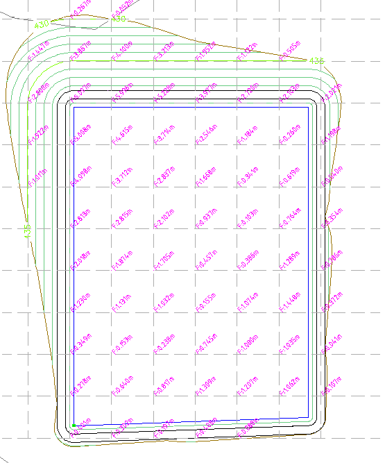
Use this command to create a grid of points across one (or two) surfaces. Typically this command is used to create Civil Points representing the elevation difference between two surfaces. Points are created on a grid with the user specifying the x (horizontal) grid and y (vertical) grid spacings, only where the surface (or the common area when two are selected) exists.
After creation, users can edit the Civil Point information via the Point Groups command to change the inputs for selecing elevations. Points can also be grip edited in the drawing.
If surface or position information changes, run the Update Points command to update elevations.
About Comparing Surfaces (Calculate Second Elevation)
In terms of the Point Properties being applied for the surface elevations, Surface 1 in the form is mapped to the Elevation property for a Point. Surface 2 in the form is mapped to the Elevation2 property for a point.
The Point Style includes mapping the Point Properties to attributed text in the block used in the Point Style - users need to set up the Elevation property to include a subtraction of the Elevation2 property. An example of this adjustment to a Point Property (the Elevation parameter) is shown, below:
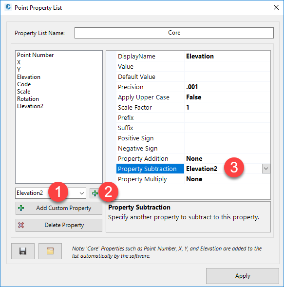
When there is an Elevation2 substraction on the Elevation point property, as shown above, this will be used to calculate the elevation difference when Surface 2 is selected.
Default Styles to show cut/fill Depths
The Point Style named Cut (C) - Fill (F) has been created as a sample of how to set up a Point Style to show elevation difference between two surfaces. If this Point Style isn't there, any one with the words cut and/or fill in them is set up to display elevation differences.
Details
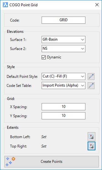
Upon selecting the command the following form is displayed:
|
|
Code |
Type in a Description for the Points |
Elevations |
Set where the point elevation information will come from. Selecting two surfaces will enable calculation of a cut/fill elevation. |
Surface 1: |
Pick the Surface for elevation information to be assigned to the point. This is mapped to the Point Property 'Elevation' |
Surface 2: |
Pick the second Surface for the elevation difference to be calculated. The elevation is calculated as Surface 1 minus Surface 2. This is mapped to the Point Property 'Elevation2' |
Style |
Set the Point Style to apply for the created point/s. |
Default Point Style |
Select a Point Style for display of the point, in the case that the point description is not found in the Code Set Table. |
|
Click to open the Point Style Editor to create/edit/manage Point Styles. |
Code Set Table |
Select a Code Set Table to apply a Point Style, Layer and Description formatting based on a matching Code. |
|
Click to open the Code Set Table to create/edit/manage point codes for auto assignment of styles, layers and description formatting. |
Grid |
Set up the grid spacing horizontally and vertically between points |
X Spacing |
Type in a value for the horizontal distance between points |
Y Spacing |
Type in a value for the vertical distance between points |
Extents |
Select the bottom left and top right extents for establishing the grid of points |
Bottom Left |
This
will report as 'Not Set' initially. Users must click on the Note: Until both of the Extents are input, users will not be able to run the Create Points button. |
Top Right |
This
will report as 'Not Set' initially. Users must click on the Note: Until both of the Extents are input, users will not be able to run the Create Points button. |
Create Points |
Click to add Civil Points to the drawing using the grid extents and x,y distances specified. |