Auto Create Grading Strings
Icon: |
|
Introduction
This command automates the process of creating grading strings by allowing the user to create gradings by selection of multiple polylines. Selection of polylines can be achieved by individual selection in the drawing or by layer/s containing polyline/s. Multiple tabs guide users through the process of selecting source geometry, defining naming conventions, setting design parameters, establishing initial grading elevations and configuring model integration.
Following creation the usual grading tools can be used - each grading string is created individually.
If the number of grading strings is large, the Manage Grading Strings command can be used to disable automatic updating of grading string models.
Workflow Example: Creating Pad Gradings
1. Select Polylines (Tab 1): Choose the layer containing your lot boundaries and click "Add Layer Polylines".
2. Set Naming (Tab 2): Enter a prefix (e.g., "PAD -"), set a start number (e.g., "1"), and enable zero-padding.
3. Configure Settings (Tab 3): Select a pad Template, the Target Surface (Existing Ground), and set Batters (e.g., Cut: 2, Fill: 2).
4. Set Initial Height (Tab 4): Select "Drape to Surface - Centroid" and choose the design surface.
5. Review Options (Tab 5): Enable "Create surfaces for each
grading"
6. Create: Click "Create Grading Strings".
Tips and Troubleshooting
Tips for Efficient Use:
• Large Batches: Disable "Update models after batch create" for maximum speed.
• Existing Gradings: Polylines highlighted in Light Yellow in the grid will be skipped by default.
• Check Names: Always use the Preview in the Naming tab.
• Zoom: Click any row in the Polyline Grid to zoom to that feature.
•
Polyline Direction: It is important to establish consisten polyline
directions to ensure that left/right templates are applied on the expected side.
Using the Edit Grading > Reverse button can rectify this, per grading string.
Troubleshooting:
• No polylines in list: Click "Refresh Layers".
• Selection fails: Ensure objects are LWPOLYLINE (not lines or splines).
• Creation fails: Verify Template and Target Surface exist.
• Names exist: Adjust Prefix or Start Number to ensure uniqueness.
Details
Upon selecting the command the following form is displayed:
|
|
|
|
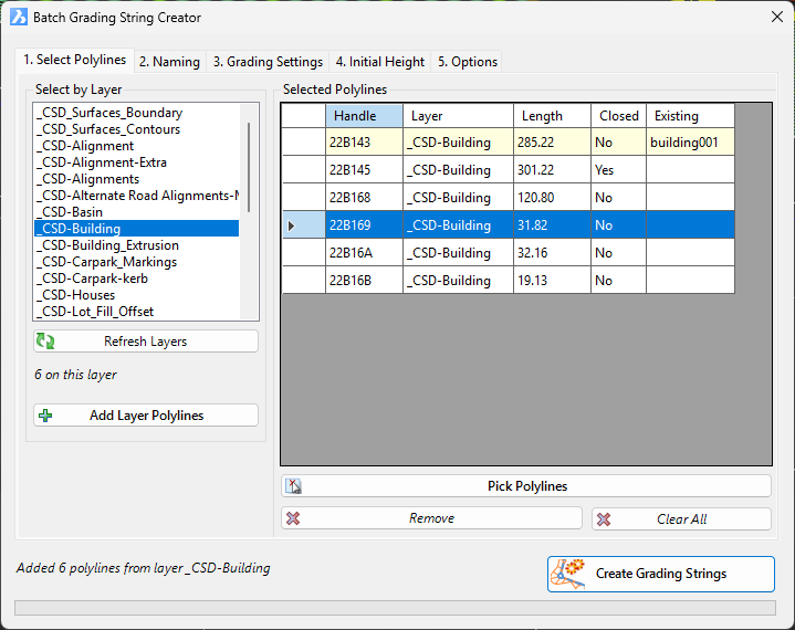
Tab 1: Polyline Selection |
Select source geometry |
|
Select by Layer [List] |
Select a layer containing polylines to process. |
|
Refresh Layers |
Updates the list of available layers from the current drawing. |
|
Add Layer Polylines |
Adds all polylines from the selected layer to the selection grid. |
|
Pick Polylines |
Allows you to select individual polylines directly in the drawing. |
|
Remove |
Removes highlighted polylines from the selection grid. |
|
Clear All |
Removes all polylines from the selection. |
|
Selected Polylines Grid |
Displays selected polylines with details like handle, layer, length, and closed status. White: Normal polyline, ready for grading. Light Yellow: Polyline already has a grading attached (skipped if "Skip existing" is enabled). Tip: Click a row to zoom to that polyline. |
|
Tab 2: Naming |
Define naming convention |
|
Prefix |
Text added before the sequential number (e.g., "PAD -"). |
|
Suffix |
Text added after the number (Optional). |
|
Start Number |
The initial number in the sequence (Default: 1). |
|
Zero-pad numbers |
When enabled, adds leading zeros to the number (e.g., "001"). |
|
Digits |
Defines the total number of digits for zero-padding (e.g., 3 -> "001"). |
|
Preview |
Shows the first 5 names that will be generated. Example 1: Prefix "PAD -", Start 1, Digits 3 = PAD -001 Example 2: Prefix "LOT", Start 10, Suffix "-A" = LOT10-A |
|
Tab 3: Grading Settings |
Geometric and design settings |
|
Target Surface |
The surface the grading will project to (e.g., Existing Ground). |
|
Template |
Select the Template (cross-section shape) to be applied. |
|
Spacing |
The distance interval between generated cross-sections along the polyline. |
|
Corner Angle Increment |
Angular resolution used for defining curves and arcs. |
|
Corner Method |
Method for handling vertices/corners: Radial, Mitre |
|
Tab 4: Initial Height |
Defines starting elevation |
|
Method |
Select the method to determine elevation: • Fixed Level: Specific elevation. • Drape (Start/End/Centroid): Uses surface elevation at specific points. • Drape (Low/High/Average): Analyses points along the polyline. • Level Difference: Sets the elevation as the diffference between two surfaces, measured at the poyline centroid |
|
Fixed Level (Value) |
The specific elevation value to use for the "Fixed Level" method. |
|
Surface for Height |
The surface to sample for all "Drape" methods. |
|
Second Surface |
The second surface required for the "Level Difference" method. |
|
Height Offset |
An additional offset value (positive or negative) added to the calculated height. |
|
Tab 5: Options |
Creation process and model integration |
|
Infill interior areas |
For closed polylines, triangulates the interior area to create a pad surface. |
|
Create surfaces for each grading |
Generates an individual DTM surface for each created grading string. |
|
Update models after batch create |
Rebuilds the design models immediately after creation. Disable this to speed up large batch operations. |
|
Skip polylines that are already gradings |
Ignores polylines that are already associated with an existing grading string. |
|
Actions |
|
|
Create Grading Strings |
Initiates the batch creation process and creates grading string/s from selected polyline/s. |
|
Cancel |
Closes the form without creating strings. |